[Partner Content] We are exposed to EMI everywhere, it is inevitable, but what is the effect of this on operational amplifiers and what can you do about it to prevent this? In this article we explain why it is important to use op-amps with a high EMIRR. Read all about it!
Operational amplifiers are very popular and often used in a variety of applications, for example to amplify a weak signal from an IoT sensor, and to collect and transmit its data by wireless communication. As for this article, we just like to highlight the effect of electromagnetic interference (EMI) on the operation of op-amps, which is almost inevitable, as we are exposed everywhere to a range of sources which are on one hand intentional, such as cell phones, radio transmitters, Wi-Fi, Bluetooth, remote controls. But on the other hand, also unintentional like system clocks, oscillators, processors, switching regulators just to name a few.
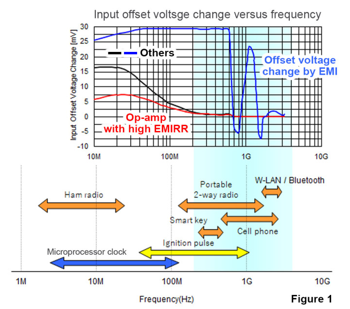
These sources of interference (Figure 1) can have any kind of frequency, from several megahertz even up to the gigahertz range, and are either conducted EMI (transmitted through connected elements) or radiated EMI (transmitted through wireless elements), like the PCB layout, cables, leads of the package and even the internal bonding wires of the chip.
How to observe the impact of EMI?
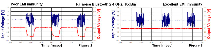
The most common effect is an output voltage offset; the AC interference is somehow rectified by internal P-N junctions and filtered by the circuit, finally it appears as an amplified output voltage offset corrupting analog measurements and/or digital data. EMI may appear on any terminal including inputs, outputs, power supply and control lines. However, in general it is assumed that the input terminal is most vulnerable to EMI influence versus other terminals. The amount of offset voltage fluctuates with the strength of the EMI interference. Figure 2 shows details of the effect of a Bluetooth RF burst causing a significant offset voltage shift in a traditional op-amp circuit.
Definition of the EMI Rejection Ratio
In many modern op-amps, measures against EMI are taken, a new term was introduced to the parameter list, called the Electro-Magnetic Interference Rejection Ratio or EMIRR in short and indicates the level of immunity to interference. The higher the EMIRR value, the smaller the offset voltage shift. Refer to Figure 3 and note that this op-amp has a high immunity for the RF burst, almost no visible evidence of any offset voltage shift on the op-amp output.
EMIRR measurement comparison
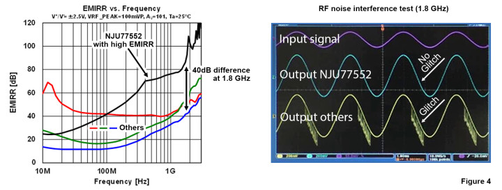
When designing an application, it is important to select the right op-amp if one expects a significant source of EMI near to the sensitive op-amp inputs. Figure 4 shows the NJU77552 with a solid EMIRR in the gigahertz range in comparison to op-amps from other brands. It is obvious that the NJU77552 filters out the interference of 2.4 GHz Bluetooth radio smoothly whilst the other product shows glitches in the output signal.
Learn more about EMIRR and other op-amp features on our website.
Operational amplifiers are one of the key selling products of Nisshinbo Micro Devices and is ranked among the global top 5 manufacturers of these devices. Its range offers a variety of features for almost any requirement:
Gain Bandwidth / Speed
Low Power / Low Current
Precision / Stability
RF Immunity
Voltage Range
I/O capabilities
Low Noise
Package Options
System Costs
Nisshinbo Micro Devices is a new brand for electronic devices and microwave products, but in fact it has over 60 years of expertise and has often pioneered the development of new semiconductor products. As of January 1, 2022, New Japan Radio and Ricoh Electronic Devices have joined forces to establish Nisshinbo Micro Devices. A comprehensive portfolio is available for consumer, industrial and automotive markets with analog components such as:
Elektor Magazine has been one of the leading sources of information on electronics for engineers, designers, start-ups and companies for 65 years. Our magazine is powered by an active community of electronics engineers – from students to professionals – who are passionate about designing and sharing innovative ideas.
For them, we publish hundreds of items a year, in formats such as articles, videos, webinars, and other learning formats. Our mission is to share knowledge in every possible way and inspire readers with the latest developments within the electrical engineering sector.
Thank you for your vote!
Leave further comments in the fields below.
Thank you for your vote!
If you wish to leave a comment with your rating, please first use the login below. If not, just close this window.


Discussion (0 comments)