Engineering in March: LoRaWAN 101, DIY Theremin, AVR SDR, and More
Each month, our editors and engineers sift through back issues of Elektor for interesting and inspiring projects from the past. Here we take a look at a few of the more memorable projects, like a DIY Theremin and an AVR SDR, from past March editions.
Each month, I sift through back issues of Elektor for interesting and inspiring projects from the past. Over the past several days, I've enjoyed the process of reviewing projects from previous March editions. I especially enjoyed looking at projects and articles from the late 1980s and early 1990s. Below I detail a few of the designs that caught my attention, including a DIY Theremin, AVR SDR, and lab power supply.
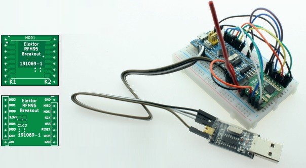
My First LoRaWAN (March 2020)
The LoRa radio technique, which covers data transmission combining long-range and low-energy consumption, is suitable for networked sensors having to economize with their energy source. The Things Network is a popular and open network that can receive sensor data and make it available worldwide. In March 2020, Elektor engineer Mathias Claussen presented an interesting starter project.
LoRaWAN project
"For the first steps with LoRaWAN, a node at around 25 euros and a gateway based on a Raspberry Pi and an RFFM95 module are all you need," Claussen explains. "However, this solution is very limited and not suitable for productive operation. If you are eager to do more with LoRaWAN after experimenting, you should exchange the gateway for a fully LoRaWAN-compatible commercial device."
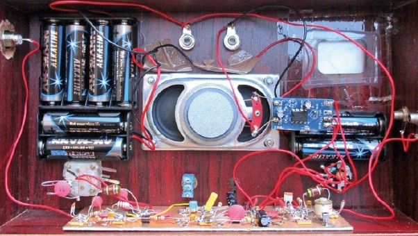
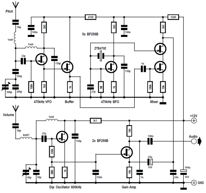
Build Your Own Theremin: Using JFETs Instead of Vacuum Tubes (March 2017)
Lev Termen’s original theremin design used vacuum tubes, but you can use JFETs. In a March 2017 article, Burkhard Kainka presented an experimental design for a compact DIY theremin.
DIY Theremin
The circuit
"The complete circuit includes the second oscillator, the mixer and a circuit for the volume antenna," Kainka explains. "The second oscillator is stabilized at 470 kHz by a ceramic resonator, and so it must be possible to set the adjustable oscillator to this frequency. A trimmer capacitor is provided for tuning."
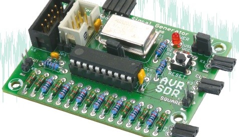
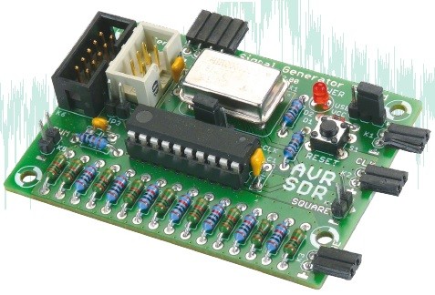
AVR SDR (March 2012)
Interested in software-defined radio (SDR)? About 10 years ago, Elektor published an article about SDR and detailed how to generate precision signals using an ATtiny microcontroller.
AVR software-defined radio (SDR)
“The signal generator board is based on an AVR microcontroller clocked at 20 MHz and an R-2R ladder forming a digital to analog converter to produce the output voltages," Martin Ossmann explained. Although it wasn't a novel circuit, Ossmann showed to use it in a variety of applications. For instance, he covered how to use it to generate outputs useful for testing other circuits, such as frequency- and phase-modulated signals. For even greater precision, he explained how to connect the signal generator to an external clock source, which was locked to a frequency standard such as the German DCF77 signal on 77.5 kHz or French TDF signal on 162 kHz.
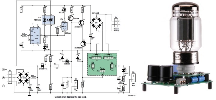
T-Reg: A High-Voltage Regulator for Valve Amps (March 2009)
Long-time Elektor readers know Jan Didden as the man behind Linear Audio. And many of you will remember my 2021 interview with him about audio electronics in the 1980s. Back in 2009, Didden presented a novel design called T-Reg, which was a high-voltage regulator for valve amps. "This being a valve regulator, there are a few other things to take care of," he explained.
High-voltage regulator for valve amps
"One is the delayed application of the anode voltage, not just for the pass device but also for the amp to be powered ... IC1 is a standard 555 (CMOS) timer that pulls down the LED in IC3 some time after the supply is switched on. The delay is set by R8 and C3 and with the given values is about 30 seconds. Once the LED in IC3 is on, the opto-triac will fire and switch on thyristor TH1, which will apply the rectified high-voltage to the pass valve."
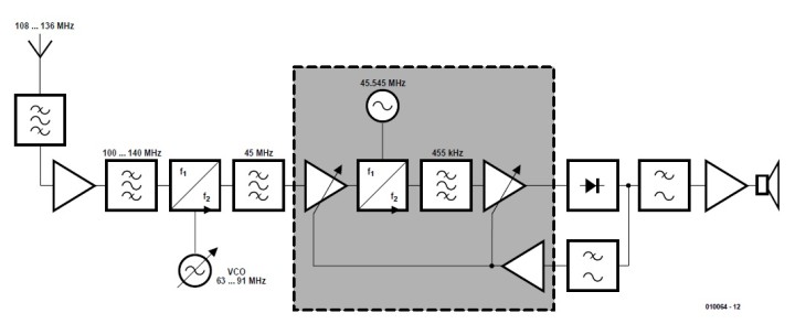
VHF Airband Receiver (March 2002)
Back in 2002, Elektor presented a design for a compact VHF airband receiver. The receiver was a double-conversion superheterodyne design with intermediate frequencies at 45 MHz and 455 kHz. Refer to the nearby diagram for the receiver's overall structure.
Overall structure
As Gert Baars explains, The RF signal picked up by the whip antenna (length approx. 60 cm) is first filtered to suppress out of band components. Then follows a 20 dB amplifier and a filter with a passband of about 100-140 MHz. The main function of this filter is to keep signals at the image frequencies double-conversion superhet for 108-137 MHz NAV and COM reception."
VHF Airband Receiver
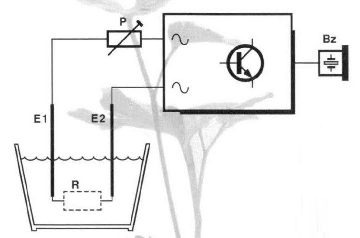
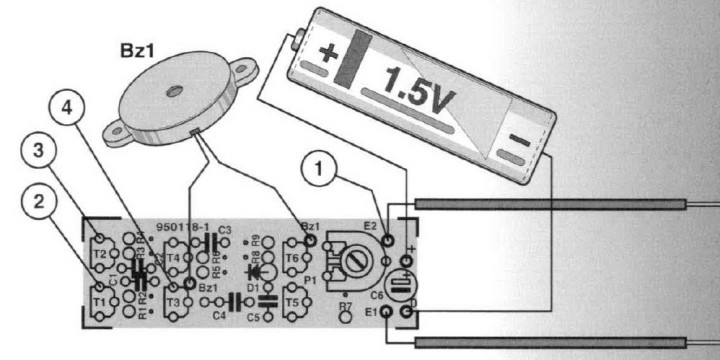
Houseplant Buzzer (March 1996)
We now have IoT solutions and apps that can manage simple tasks and remind us of all sorts of things. But back in 1996, we didn’t have apps so many out-of-the-box solutions, which is why Elektor engineers and readers had to design their own answers to everyday problems. This houseplant buzzer is one such project. The circuit monitors soil moisture and sounds an alarm when it gets too dry.
Houseplant buzzer circuit
"The electrical resistance, R, of the soil is measured by a pair of sharp pointed probes, El and E2, which are pushed into the soil," P. Kersemakers explained. "The resistance is continually monitored by a simple circuit. When the soil gets (too) dry, this circuit actuates a piezo-electric buzzer, Bz.”
Houseplant buzzer details
The houseplant buzzer is based on the property of moist soil being electrically conductive. The potential developed across the soil resistance R is measured via probes El and E2. If the soil is dry(ish) (R = high), a buzzer sounds.
pH Meter (March 1985)
Chemists have been using electronic systems to measure things like pH for decades. In 1985, Elektor presented an affordable pH meter design for engineers, hobbyists, and aquarium owners alike.
pH meter project
The pH meter’s circuit diagram is based on a special IC which processes the voltages provided by a pH sensor and a temperature sensor: the results are presented on a 3.5-digit LCD.
pH meter circuit
"The circuit of the pH meter uses a special voltmeter IC and is therefore quite straightforward," Elektor explained in the article. "This chip, ICI, contains a dual-slope analogue/digital converter and a complete LCD drive stage. Capacitor C2 is a memory for the autozero function in the IC. Capacitor C3 is an integrator which is charged via RI. Reference capacitor Cl is also part of the dual-slope integrator. The battery is connected to the IC (pins 1 and 26) via switching transistor T1."
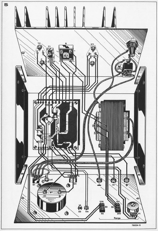
Robust Lab Power Supply (March 1979)
Elektor engineers and readers have always had the DIY spirit. Sure, there are tons of off-the-self solutions that are ready to go right out of the box. But many times it is more fun to build your own equipment. In March 1979, Elektor presented a DIY lab power supply project. The nearby image show the PSU’s wiring details.
PSU power supply
“Until only a few years ago, power supply units almost exclusively employed discrete regulator circuits,” Elektor noted. “However with the advent of cheap universal precision voltage regulator ICs, it has become possible for the amateur to build an inexpensive PSU enjoying the specifications which previously were the preserve of expensive professional equipment.
More Engineering Headed Your Way
Join us next month when we highlight more classic Elektor articles, projects, and tutorials. And don’t forget to share your thoughts in the comments section below. The engineering continues!
Elektor Magazine has been one of the leading sources of information on electronics for engineers, designers, start-ups and companies for 65 years. Our magazine is powered by an active community of electronics engineers – from students to professionals – who are passionate about designing and sharing innovative ideas.
For them, we publish hundreds of items a year, in formats such as articles, videos, webinars, and other learning formats. Our mission is to share knowledge in every possible way and inspire readers with the latest developments within the electrical engineering sector.
Thank you for your vote!
Leave further comments in the fields below.
Thank you for your vote!
If you wish to leave a comment with your rating, please first use the login below. If not, just close this window.


Discussion (2 comments)