Engineering in May: DIY LiPo Supercharger, the QuadroWalker Robot, '80s-Era AI, and More
Let's review a few interesting Elektor articles from previous May editions. We've got something for everyone, including the DIY LiPo Supercharger Kit, a microphone preamp, the QuadroWalker robot, a 89C51 Flash programmer, and an overview of 1980s-era developments in AI.
Want to learn about some projects from previous May editions of Elektor? Below we highlight some notable articles and engineering projects dating all the way back to 1979. Feeling inspired? Please share your ideas in the Discussion section at the bottom of this article.
DIY LiPo Supercharger Kit (May 2021)
In 2021, Elektor colloboarated with GreatScott! — a well-known DIY electronics-focused YouTuber — to develop a battery-powered rechargeable power supply that can use widely available lithium batteries. The easy-to-use kit gives you fast access to the world of SMD soldering, with carefully chosen 1206 components and a partially assembled PCB.
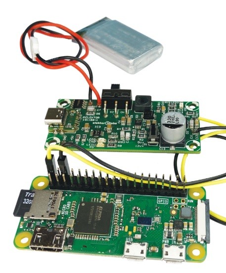
Raspberry Pi Zero powerd by DIY LiPo Supercharger Kit
As Elektor engineer Mathias Claussen explains, having a portable power source at hand, especially with switchable output voltages, is extremely useful. The nearby photo shows a Raspberry Pi Zero powered by the DIY LiPo Supercharger Kit.
Audio Engineering: Mic Preamp (May 2017)
Audio engineering has always been a hot topic in Elektor circles. In 2017, Joseph Kreutz presented readers with an compact microphone preamp with professional specifications. In addition to detailing the design and construction process, Kreutz also offered an in-depth analysis of preamp noise, complete with diagrams and essential equations.
The heart of this amplifier is the op-amp.
The use of a transformer (TR1) makes it possible to design a simple circuit with effective input isolation and good common-mode signal rejection," he explained. "The transformer substantially reduces interference, such as that caused by cellphones. It’s easy to find microphone transformers with a 1:10 ratio. This type of transformer steps the signal voltage up by 20 dB, which considerably improves the preamp’s signal-to-noise ratio."
He spent about €270 and five hours on this entry-level project.
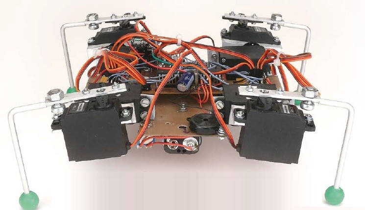
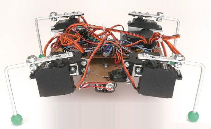
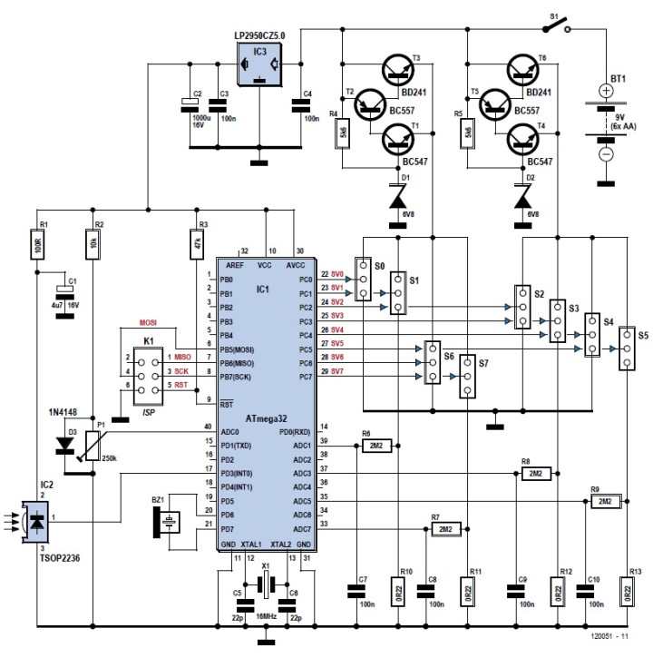
QuadroWalker (May 2012)
Looking for a fun robotics project? The QuadroWalker is a small four-legged robot featuring eight servos. A microcontroller takes care of servo control and the other functions. Not many I/O lines were required, but the author, Ger Baars, already had a small board containing an ATmega32, which he used.
The servos are attached with the aid of a few pieces of angle bracket.
"The design of the robot can be divided into three parts: mechanical, electronics and software," he explained.
The design featurs an ATmega32. Two voltage regulators take
care of the power supply for the servos.
"The mechanical part takes care of attaching the base plate to the legs via the servos. The servos also have to be joined together. This requires the manufacture of a few mounting brackets, two right-angle brackets for four servos to attach them to the base plate. Also, for each pair of servos a bracket to allow them to move at right angles with respect to each other (this kind of bracket is available for sale for certain types of servos) and a bracket to attach the leg to the second servo."
Working with a Touch Screen (May 2000)
Today, touch screens are everywhere, from smartphones to vending machines. But back in May 2000, the technology was more of a curiosity. Fortunately, Elektor was ahead of the engineering curve, and we published an intersting article that year about touch screens, touch point computation, and position detection.
Schematic diagram of the touch screen circuit.
The circuit presented in this article makes it very easy to use a touch screen in your own projects. All that you need is a single IC, which is a standard microcontroller costing only a few pounds. The circuit is self-calibrating and very energy efficient.
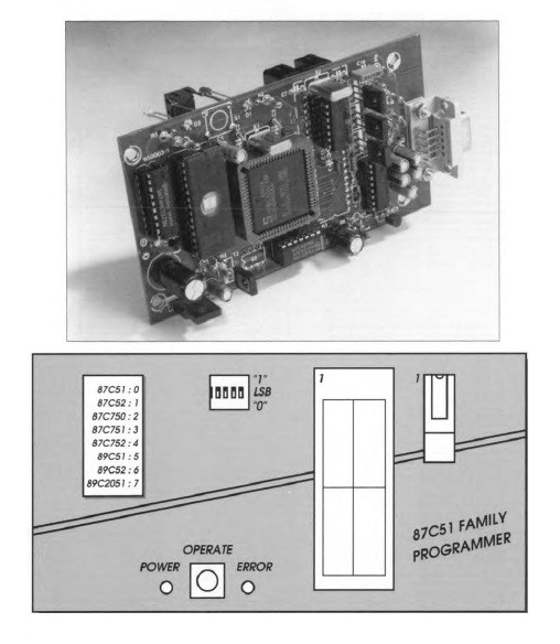
Programmer for 87/89C51 Series Flash Controllers (May 1995)
On the cover of the May 1995 issue, we featured an up-close image of an 89C51 Flash programmer. With the project, programming EPROM and Flash memory-based microcontrollers from the MCU-51 family was within reach of any electronics enthusiast.
"Although the circuit is fairly extensive, its operation is easy to understand," K. Walraven wrote. "As already mentioned, the entire programming operation is controlled by IC1, an 80C451 running at a clock speed of 14.75 MHz."
The top image shows the prototype board. The bottom diagram is the s
programmer's front panel.
"This frequency is used to enable the controller to communicate with a PC at 9,600 baud (a standardized bit rate). It also allows a number of frequeneies needed for the programming process to be derived easily. The controller fetehes its instructions from an EPROM (IC3) via a latch (IC2) which separates the multiplexed address/data information. Since the programmer communicates with a PC via the RS232 port, a MAX232 line driver/interface is used. The rest of the circuit consists of a power supply and an array of electronic switches which ensure that the programming socket pins receive the right signals."
Artificial Intelligence (May 1988)
Did you know that Elektor was publishing about artificial intelligence back in the 1980s? In May 1988, we ran an interesting article in which the author, M. Seymour, outlined a dream: "that one day it may be possible to build a machine that can think, that is, need not be programmed to perform its functions. After going into a bit of machine intellience history, Seymour covers '80s-era research and development relating to the topic.
"A technology that was originally developed in the 1950s, but was abandoned after 10 years, has recently been revived. It is called neural computing and could be of inestimable value in the creation of true artificial intelligence. Neural computers attempt to copy the human brain and are quite unlike conventional computers, because they are not programmed, but can learn by example."
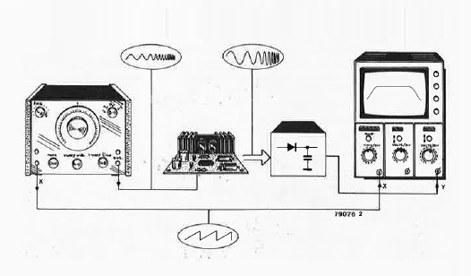
Sweep Generator (May 1979)
What is a sweep generator and what can you use it for? Back in May 1979 article on the subject, Elektor author L. Koppen dove into the details.
How a sweep generator displays frequency response.
The image above illustrates illustrates how a sweep generator is used to display the frequency response of an amplifier on an oscilloscope. With the aid of a sweep generator and an oscilloscope the same measurement can be carried out virtually automatically. The sweep generator provides a sinewave output signal, the frequency of which increases continuously, and a sawtooth signal which is used as an external timebase input for the scope.
More Engineering to Come
Join us in June when we highlight more classic Elektor articles, projects, and technical tutorials. Be sure to share your thoughts in the comments section below. The engineering never stops!
Elektor Magazine has been one of the leading sources of information on electronics for engineers, designers, start-ups and companies for 65 years. Our magazine is powered by an active community of electronics engineers – from students to professionals – who are passionate about designing and sharing innovative ideas.
For them, we publish hundreds of items a year, in formats such as articles, videos, webinars, and other learning formats. Our mission is to share knowledge in every possible way and inspire readers with the latest developments within the electrical engineering sector.
Thank you for your vote!
Leave further comments in the fields below.
Thank you for your vote!
If you wish to leave a comment with your rating, please first use the login below. If not, just close this window.


Discussion (0 comments)