Engineering in the Fall: An ELF receiver, a DIY barometric altimeter, and more
Looking for the perfect fall engineering project? Check out the following projects and articles from past September and October editions of Elektor. We found them inspiring. What do you think?
Looking for the perfect fall engineering project? Check out the following projects and articles from past September and October editions of Elektor. We found them inspiring. What do you think?
USB to S/PDIF Interface (2020)
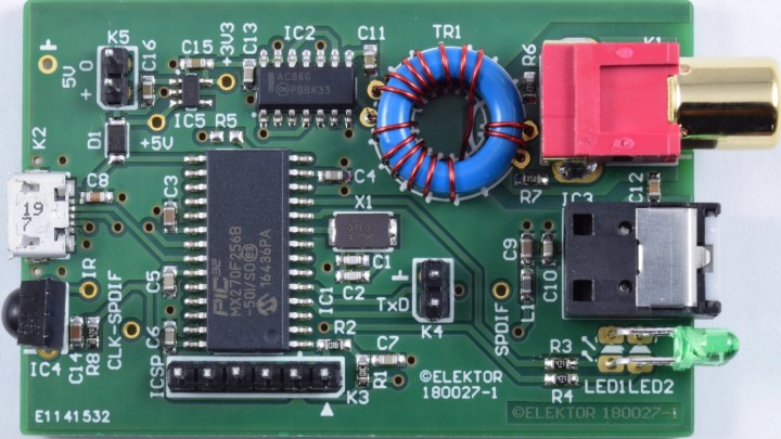
Most PCs and mobile devices, such as tablets and smartphones, don't have a real audio output. Instead, they have a multifunction USB connector and a headphone output, which can be insufficient when you want to connect one of these devices to a high-quality amp or an AV receiver. Fortunately, you can solve this problem with a high-quality USB to S/PDIF interface.
High-quality USB to S/PDIF interface
"The circuit that we describe here is a USB to S/PDIF converter," explains Stephan Lück. "The converter is easily connected to a PC or similar devices using the USB connector. The S/PDIF output allows it to be connected to AV receivers, high-end amplifiers, or stand-alone audio DACs. The S/PDIF output is implemented twice (both electrical and optical) and remote control is possible thanks to an IR-receiver."
What are the lowest frequencies of all EMI signals? Are they those generated by electrified railways? Nope! According to Kurt Diedrich, "you can receive some extremely interesting signals between 0 Hz and the 'railway' frequency of 16 2/3 Hz." You can use the receiver he describes with an ADC module and some free PC software to receive and record these signals.
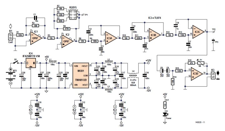
Schematic of the ELF receiver (without data logger)
"The receiver described here operates in conjunction with the ADC module described in a separate article, an Arduino Uno and some free—that goes without saying—recorder software for the PC. This combination makes it possible to detect, display and log weak alternating currents and/or alternating magnetic fields at frequencies down to less than 1 Hertz. The receiver output can additionally be connected to other recording devices, all the time keeping in mind that signals below 16 Hz will be attenuated heavily by PC sound cards."
Barometric Altimeter (2009)
Today, we can use our smartphones and smartwatches to acquire quite a bit of info about our environment in real time. Engineering solutions abound. But back in 2009, it wasn't as easy. But you could DIY, as C.V. Niras proved with his barometric altimeter design.
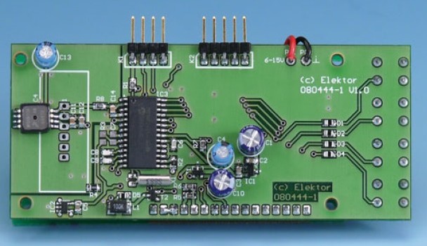
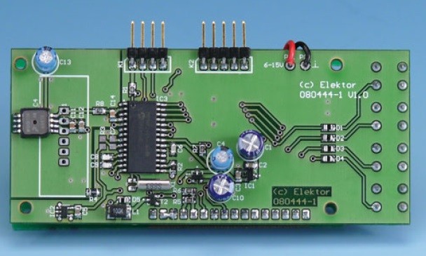
Finished board with MPXHZ6115A SMD pressure sensor mounted at far left of the board.
"Since barometric pressure is closely approximated by the hydrostatic pressure caused by the weight of the air above you, your altitude on the planet above a reference level can be calculated fairly easily and shown on a display. The altimeter described here is calibrated to show your altitude above the mean sea level (MSL) based on a mathematical model called International Standard Atmosphere (ISA). The ISA model describes the troposphere range with a linear temperature distribution and although that’s unlikely to change with time, it does as a function of temperature, with barometric pressure as an inherent dependency. Right, this project does take temperature deviation into account to compensate the altitude reading!"
Fingerprint as Password: Fingerprint-Based Authenticaion (2005)
In 2022, many of us use fingerprint authentication to access our laptops, smartphones, and apps (e.g., banking). But did you know that Elektor was covering fingerprint sensing and authentication way back in 2005? That was two years before the first iPhone hit the market! Check it out. In the article, Helmuth Lemme prognosticates that fingerprint sensors "will increasingly be used for securing financial transactions at cash machines and for on-line banking. In the future the fingerprint of the owner will be securely stored in identity cards and credit cards, and they will also be used for authenticating e-mails using digital signatures."
Learn how fingerprint-based authentication works.
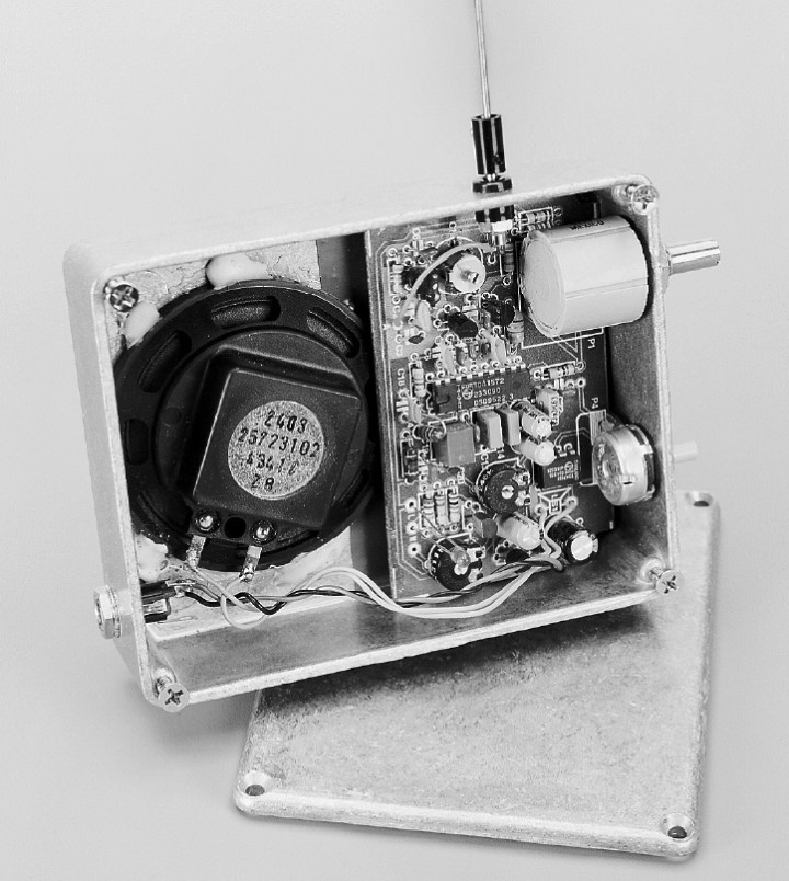
Poor Man’s Short-Wave Radio (1999)
If you are interestedin radio-frequency engineering, you will enjoy the this tiny receiver from 1999. Constructed on a 8.5 × 5 cm PCB, the radio consists of a few components, a whip antenna at the input, and a small loudspeaker at the output.
The circuit is based essentially on a Type TDA1572 integrated AM receiver.
Some parameters:
Frequency range: approx. 5.5-12.5 MHz
Sensitivity (6 dB signal-to-noise): approx. 1 μV
AGC range: 86 dB
Intermediate frequency: 455 kHz
Audio power output: 1 W into 8 Ω
Quiescent current drain: approx. 50 mA
Supply voltage: 12–15 V
As G. Baars explains, the design "receives broadcasting stations from all over the world: the Voice of America; Radio Moscow; Radio Prague, not forgetting the BBCWorld Service when you’re on holiday. And all that with a minimum of controls."
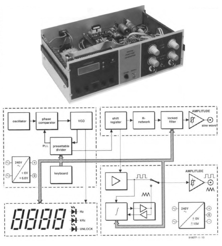
Digital Function Generator (1991)
Check out this cover project from 1991. In the article, T. Giffard presents a digital function generator for test and design. The design is based on four printed-circuit boards.
The digital lunction generator (top) and its block diagram (bottom).
"The heart of the frequency-synthesis board at the top left is the phase-locked loop (PLL)," Giffard explains. "A phase comparater compares the output frequency of a crystal oscillator with that of a voltage-controlled oscillator (VCO). Any phase d ifference between the two signals causes the comparator to generate a voltage that is used to synchronize the VCO with the reference oscillator."
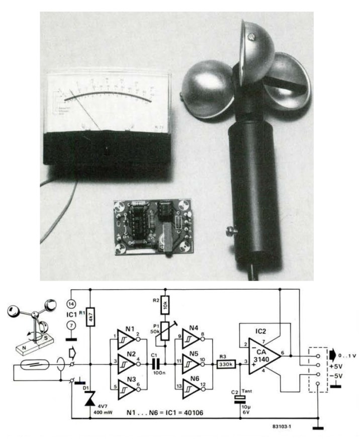
Anemometer: Wind Speed on a Moving-Coil Meter (1983)
Electronic solutions have been implemented in the field of meteorology for decades. Take this anemometer project from 1983, for instance. While it is true that the rotating mechanical element is still an essential part of the instrument, the bulk of the work is now done by electronic components. More than an instantaneous wind velocity meter, the design also stores the maximum and minimum values measured over a certain period of time.
Wind speed on a moving-coil meter
"The anemometer described here uses a magnet to open and close a reed switch once per revolution of the mill. This information can be processed electronically so that the speed of the wind causing this rotation can be shown on a moving coil meter or a display. It is interesting to be able to see not only what the instantaneous wind speed is, but also the maximum and minimum values measured over a certain period of time. This is a feature of the circuit that should appeal especially to amateur meteorologists."
More Projects, More Engineering
Next month, we will highlight more classic Elektor projects, articles, and engineering tutorials. If you have any ideas, questions, or feedback, please share your thoughts in the comments section below. The engineering continues!
Elektor Magazine has been one of the leading sources of information on electronics for engineers, designers, start-ups and companies for 65 years. Our magazine is powered by an active community of electronics engineers – from students to professionals – who are passionate about designing and sharing innovative ideas.
For them, we publish hundreds of items a year, in formats such as articles, videos, webinars, and other learning formats. Our mission is to share knowledge in every possible way and inspire readers with the latest developments within the electrical engineering sector.
Thank you for your vote!
Leave further comments in the fields below.
Thank you for your vote!
If you wish to leave a comment with your rating, please first use the login below. If not, just close this window.


Discussion (0 comments)