How-To: Calculate the Prospective Short-Circuit Current or PSCC
The prospective short-circuit current (PSCC) is the maximum current that can flow through a shorted electrical circuit. The PSCC value is needed for selecting devices like circuit breakers and fuses to protect the circuit. So how does this work?
The prospective short-circuit current (PSCC) is the maximum current that can flow through a shorted electrical circuit. PSCC is also known as available fault current or short-circuit making current. As with any current it conforms to Ohm’s law. Therefore, the circuit’s supply voltage and its impedance determine the PSCC value.
Why would I want to know the PSCC?
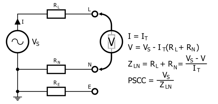
To select devices like circuit breakers and fuses that will protect the circuit, you need the PSCC value. Such devices must be able to sustain the PSCC to provide a reliable protection. If the breaking capacity or interrupting rating of the protective device is too low, the PSCC may destroy it or cause an electric arc. In either case the breaking device may not operate correctly, and dangerous situations may arise. Open-loop voltage measurement (left) & closed-loop short-circuit current (right).
What about the Trip Current?
Note that the breaking capacity of a circuit breaker is not the same thing as its trip current. For instance, the SN201 L C32-L 1+N pole miniature circuit breaker (MCB) from ABB has a rated trip current (In) of 32 A and a rated short-circuit current (Icn) of 4.5 kA (at 230 / 400 VAC). This is because the short-circuit current depends on the capacity of the power source and is unrelated to the load current which the circuit breaker protects.
Measuring the PSCC
You can measure the PSCC of an electrical installation with a so-called PSC Tester. This is an easy-to-operate instrument that calculates the PSCC value of a circuit in amperes and kiloamperes. Although pressing the Test button is usually enough to obtain a value, connecting the instrument properly to the system requires knowledge of what you are trying to measure. The PSC Tester makes a test current of a known value flow to calculate the circuit's impedance.
What does a PSC tester do?
A PSC tester first measures the open-circuit voltage at the terminals (VS). Then it applies a small load for a short time to make a current of a known value flow through the circuit (IT). The value depends on the selected measurement range and goes from 2 A, say, up to 25 A or more. The measurement duration also varies with the range and is a few tens of milliseconds. For some real data, see the tables at the end of the article.
With the test current flowing, the tester measures again the voltage V at the terminals. Due to the impedance (ZLN) of the circuit, V will now be a bit lower than VS. The impedance ZLN equals (VS - V) / IT. By assuming that ZLN is constant, the tester calculates the PSCC as VS/ZLN.
What is Loop Testing?
PSC testers can also measure the earth fault loop impedance ZS or ZE or the prospective fault current PFC (or PEFC). This corresponds to the impedance of the circuit between the phase and the earth conductors in the event of a short between the two. A low impedance will result in a high fault current making a protective device trip quickly. It also helps to ensure a small potential difference between the earth conductor at the outlet and the earth you are standing on.
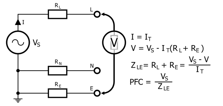
When measured at an outlet, the earth fault loop impedance is called ZS; when taken at the supply’s entry point, it is called ZE. As such ZS = ZE + RL + RE, with RL and RE the respective impedances of the phase and earth conductors between the supply entry point and the outlet. Calculating the prospective earth fault impedance ZS (or ZE) or the earth fault current P(E)FC.
Calculate the PFC
The earth fault loop impedance is measured in the same way as the PSCC, but again depending on the selected range, the test current can be much smaller (as low as tens of milliamperes). Also, take the measurement between the phase and the earth conductors instead of between phase and neutral. The P(E)FC is obtained by calculating VS / ZLE.
Can you show some real data?
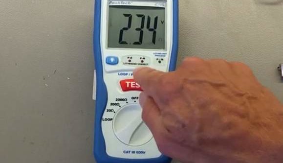
Here is a video demonstrating the PeakTech 2715 Loop and PSC Tester.
The tables below show the measurement characteristics of the PeakTech 2715 as taken from the user's manual.
Loop resistance
Range
Resolution
Test time
Full scale accuracy
20 Ω
0.01 Ω
25 A / 20 ms
±2% of F.S ±5d
200 Ω
0.1 Ω
2.3 A / 40 ms
±2% of F.S ±5d
2000 Ω
1 Ω
15 mA / 280 ms
±2% of F.S ±5d
Prospective short current
Range
Resolution
Test time
Full scale accuracy
200 A
0.1 A
2.3 A / 40 ms
±2% of F.S ±5d
2 kA
1 A
25 A / 20 ms
±2% of F.S ±5d
20 kA
10 A
25 A / 20 ms
±2% of F.S ±5d
Notes
When the PSCC and PFC values differ, use the highest value for specifying circuit breakers;
Working on live electrical installations can kill you. We warned you.
Elektor Magazine has been one of the leading sources of information on electronics for engineers, designers, start-ups and companies for 65 years. Our magazine is powered by an active community of electronics engineers – from students to professionals – who are passionate about designing and sharing innovative ideas.
For them, we publish hundreds of items a year, in formats such as articles, videos, webinars, and other learning formats. Our mission is to share knowledge in every possible way and inspire readers with the latest developments within the electrical engineering sector.
Thank you for your vote!
Leave further comments in the fields below.
Thank you for your vote!
If you wish to leave a comment with your rating, please first use the login below. If not, just close this window.


Discussion (0 comments)