
Small Circuits Revival (32): Adjustable Low-noise Dual Power Supply
on
Adjustable low-noise dual power supply
idea: Hesam Moshiri
It is essential for every electronics hobbyist to have a dual, low-noise power supply. However, beginning hobbyists are (understandably) reluctant to immediately spend a lot of money on a more or less professional power supply. Nevertheless, it is perfectly possible to build a suitable (at least for the initial steps down the electronics path) power supply yourself – take a look at the schematic below.
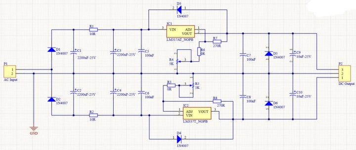
A dual (positive and negative) power supply generally uses a mains transformer with two secondary windings; however, here it is sufficient to use a simple mains transformer with only one secondary winding; this is connected to connector P1.
Diodes D1 and D2 form the rectifier. R1, R2 and C1 through C6 together form a low-pass filter that ensures that the actual regulators (IC1 and IC2) receive a nicely smoothed input voltage. Both these ICs belong to the family of ‘three-legged regulators’, with the understanding that with these particular types the output voltage is adjustable. R4 adjusts the positive output voltage and R5 the negative output voltage.
Diodes D3 and D4 protect the ICs from discharging the output electrolytic capacitors into the outputs of the ICs when the power supply is switched off.
You may well question the function of both the ‘zero-ohm resistors’ R3 and R6; the author has designed a real circuit board for his implementation of the circuit (unfortunately we cannot offer you the files for this) and this circuit board required a couple of wire links. That is why.
Depending on the transformer used, the output voltage is adjustable from ±1.25 V to ±25 V with a maximum output current of 300 to 500 mA.
The author has put together an instructional video about this circuit that you can view here. You can download the schematic in its original size below.
Discussion (0 comments)