
My journey into the Cloud (8); a simple user protocol
May 11, 2016
on
on
In the last installment with the help of an open-source library I was able to program an MQTT client for Android. Now I can send out text messages via a public MQTT broker on the internet to an MQTT client on my PC. The program running on the PC then passes the message via its USB port on to SAM-D20 board and an expansion card fitted with relays. Relays wired in parallel with the on and off push buttons on a hand held remote control unit can now be activated to turn any equipment, plugged into the remotely controlled mains outlet, on and off. To turn it on, relay 1 is activated for a short period and then deactivated. Relay 0 is switched in the same way to turn the equipment off.
With the SAM D20 running the elektor Standardfirmware (already described in elektor) relay 1 can be controlled via the serial interface using text commands such as ‘R 0 1 +’ to activate the relay and ‘R 0 1 –’ to deactivate it. The whole operation is however not exactly user friendly. The standardfirmware requires a rather clumsy sequence of commands from the MQTT communications. To switch on the remote controlled mains outlet I need to enter two MQTT messages, and press the PUBLISH button after each one:
R 0 1 + [PUBLISH] R 0 1 – [PUBLISH]
Its all a bit clunky, how could we make a more convenient user interface for my smartphone? I guess in an application like this it would be useful to be able to switch several lights or appliances on and off. It’s also possible that some lamps would be dimmable so it would be nice to be able control these also by say entering the brightness value in the range from 0 to 255. To control colored lights with RGB LEDs we can just use three values from 0 to 255, one for each of the three colors.
After a little thought I came up with a pretty basic protocol using just two bytes to send two hexadecimal values, for example ‘0503’. The first byte indicates the channel or controller number indicating which appliance is switched or controlled. The second byte contains the value which I’ve called ControllerValue. Anyone who’s dabbled with DMX or MIDI systems will recognize that this little protocol could also be used to control lighting or electronic musical equipment.
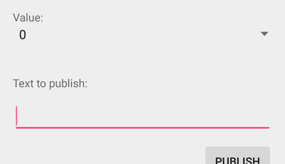
I then designed a small user interface for my Android MQTT client (see pic) to handle the CCProtocol . Right at the top the ControllerNumber is selected, for example enter 6 and now with the ON / OFF buttons you can control lamp 6. Pressing ‘ON’ sends the text ‘06FF’ (ControllerValue FF = 255 or maximum ON) and pressing ‘OFF’ sends the text ‘0600’ to the internet. To send an intermediate value (for dimming) we can just choose a value from the ‘Value’ dropdown box so by choosing ‘3’ for example, the text ‘0603’ will be sent. I have retained the text box and PUBLISH button from the previous Android MQTT Messengers version so that we can still send text over MQTT.
Now where can we select the Topic and publish the reports? This is organized in the Settings menu. To select a Topic go to the menu button at the top right of the screen and select ‘Settings’. Now choose ‘Set Topic’ and enter the topic name in the popup dialog box. The complete Topic is, as always made up of the following combination:
‘/ElektorMyJourneyIoT/’ + Topic + ‘/test’
If for example we want to enter the topic ‘lamp’ then we can select this topic in the ‘Topic to subscribe’ in the MQTT client on the PC and click on Subscribe button. The entire topic ‘/ElektorMyJourneyIoT/lamp/test’ is then setup on the PC and it can receive messages from the mobile phone.
In order for me to be able to switch the remote controlled outlet on with the command ‘00FF’ and off with ‘0000’ it was necessary to make some changes to the Atmel board firmware. This firmware together with the MQTT client for Android and the PC can be downloaded below.
In the next installment we continue with development and present an optimization of the electronics. Our next target is to hook up the controller board directly to the network!
With the SAM D20 running the elektor Standardfirmware (already described in elektor) relay 1 can be controlled via the serial interface using text commands such as ‘R 0 1 +’ to activate the relay and ‘R 0 1 –’ to deactivate it. The whole operation is however not exactly user friendly. The standardfirmware requires a rather clumsy sequence of commands from the MQTT communications. To switch on the remote controlled mains outlet I need to enter two MQTT messages, and press the PUBLISH button after each one:
R 0 1 + [PUBLISH] R 0 1 – [PUBLISH]
Its all a bit clunky, how could we make a more convenient user interface for my smartphone? I guess in an application like this it would be useful to be able to switch several lights or appliances on and off. It’s also possible that some lamps would be dimmable so it would be nice to be able control these also by say entering the brightness value in the range from 0 to 255. To control colored lights with RGB LEDs we can just use three values from 0 to 255, one for each of the three colors.
After a little thought I came up with a pretty basic protocol using just two bytes to send two hexadecimal values, for example ‘0503’. The first byte indicates the channel or controller number indicating which appliance is switched or controlled. The second byte contains the value which I’ve called ControllerValue. Anyone who’s dabbled with DMX or MIDI systems will recognize that this little protocol could also be used to control lighting or electronic musical equipment.
I then designed a small user interface for my Android MQTT client (see pic) to handle the CCProtocol . Right at the top the ControllerNumber is selected, for example enter 6 and now with the ON / OFF buttons you can control lamp 6. Pressing ‘ON’ sends the text ‘06FF’ (ControllerValue FF = 255 or maximum ON) and pressing ‘OFF’ sends the text ‘0600’ to the internet. To send an intermediate value (for dimming) we can just choose a value from the ‘Value’ dropdown box so by choosing ‘3’ for example, the text ‘0603’ will be sent. I have retained the text box and PUBLISH button from the previous Android MQTT Messengers version so that we can still send text over MQTT.
Now where can we select the Topic and publish the reports? This is organized in the Settings menu. To select a Topic go to the menu button at the top right of the screen and select ‘Settings’. Now choose ‘Set Topic’ and enter the topic name in the popup dialog box. The complete Topic is, as always made up of the following combination:
‘/ElektorMyJourneyIoT/’ + Topic + ‘/test’
If for example we want to enter the topic ‘lamp’ then we can select this topic in the ‘Topic to subscribe’ in the MQTT client on the PC and click on Subscribe button. The entire topic ‘/ElektorMyJourneyIoT/lamp/test’ is then setup on the PC and it can receive messages from the mobile phone.
In order for me to be able to switch the remote controlled outlet on with the command ‘00FF’ and off with ‘0000’ it was necessary to make some changes to the Atmel board firmware. This firmware together with the MQTT client for Android and the PC can be downloaded below.
In the next installment we continue with development and present an optimization of the electronics. Our next target is to hook up the controller board directly to the network!
Read full article
Hide full article
Discussion (3 comments)