
My Journey into the Cloud (23): Sensor values sent to Cloud using an ESP32 Pico kit
March 7, 2018
on
on
In the last installment, we built a small device using the ESP32 DevKitC, an RGB LED and a light-dependant resistor (LDR). This device periodically measures the ambient brightness level and sends this value to the AllThingsTalk cloud platform where the values are displayed on a user-configurable web page. For this to work, the ESP32 must first log in to a Wi-Fi network, then connect via TCP / IP and MQTT to the AllThingsTalk MQTT broker. Once all the connections have been successfully established, the RGB LED on the device shows a pulsing green signal. The ambient brightness level is measured every two seconds using the ADC in the ESP32 and then published via MQTT. The necessary configuration parameters (e.g. the Wi-Fi SSID) can be entered into the system using a web page, which the ESP32 supplies on its own locally generated Wi-Fi network.
So far, so good, but I still haven’t implemented any recovery mechanisms to take care of communication interruptions. During the system trials in the last installment I let the device run for half a day until my power bank battery ran down (we need to take care of power conservation issues in a later episode). The system was however not able to recognize when the Wi-Fi link was interrupted. The green LED continued pulsing, but values were no longer being supplied to AllThingsTalk. A useful and practical data logger needs to be more fault-tolerant.
I assume that it has probably dropped out of the Wi-Fi network, if connection via MQTT is not achieved after pinging.
Now I still need to check regularly in the main loop if
change of state has occurred, after a (re) attempt to login.
Finally I also assigned sensor value publishing process and the web server code routines to their own functions. This makes the main loop less cluttered and more compact, as you can see in this screenshot.
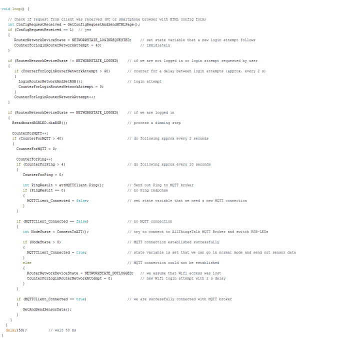
In the code you can see the use of three counters and setting of the two state variables MQTTClient_Connected and RouterNetworkDeviceState. The setup function has also been slimmed down (this new sketch is, as usual available for download, see below). Finally, I converted my small Wi-Fi network library into a class library - similar to the changes I made in the last installment for the TCP / IP and MQTT functions. The files WiFiNetwork.h/.c are located in a folder of the same name, which must be located in the libraries folder of the Arduino environment during compilation. I have extracted the serial outputs from the functions and moved them to the main program. For this, I have also created the function GetOwnIPAddressInRouterNetwork() which returns the address of the ESP32 in the router network. The calls to the Wi-Fi network functions are now done in the object-oriented notation, for example
These changes do not provide any additional functionality to the project and may seem a bit tedious to implement - but we will benefit from the increased software modularity when we port it to other platforms.
The same sketch was loaded 1: 1 to the new board, I couldn’t find any changes that would be required. It was only necessary to identify the corresponding pin header positions and link them out to the breadboard. Instead of pin 12, I connected the red test LED to pin 15 (and changed the code accordingly). One other change is necessary following a power supply outage: now you need to press the EN button, otherwise the program does not start.
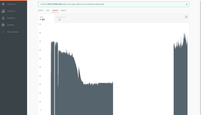
During operation, the regular pinging activity causes a brief interruption of the cyclic LED dimming process. More information on this can be found at the end of the last episode. I carried out some trials over a complete day; during that time I periodically shut down the Wi-Fi network to simulate a dropout. On my AllThingsTalk website I have organized the sampled and published sensor values as a bar chart. In the screenshot at the beginning of the article, you can see how it slowly became dark during the afternoon in my ‘home office’. When I turned on the room light at around 6:00 pm, a small peak in the measured brightness was measured.
Stay tuned for the next installment!
So far, so good, but I still haven’t implemented any recovery mechanisms to take care of communication interruptions. During the system trials in the last installment I let the device run for half a day until my power bank battery ran down (we need to take care of power conservation issues in a later episode). The system was however not able to recognize when the Wi-Fi link was interrupted. The green LED continued pulsing, but values were no longer being supplied to AllThingsTalk. A useful and practical data logger needs to be more fault-tolerant.
Pings from the ESP32
When publishing an MQTT message, the broker does not return any bytes as an acknowledgement. MQTT does however offer a ping mechanism to determine if an MQTT connection is still established. I first integrated a regular ping with the AllThingsTalk Broker into my Arduino sketch. In order to cut down on the traffic, it’s only necessary to ping after every fifth sensor value is sent; this can easily be achieved using a small software counter. I implemented the counter and called the ping at the very beginning in the main loop code section, where the LED dimming and MQTT functions are called. If a ping fails, MQTTClient_Connected variable is reset from true to false which is its value assigned at startup. This is then followed in the sketch by the code section, where connection with the Broker is initiated. I did not have to change much here; if it was unsuccessful I added the stateRouterNetworkDeviceState = NETWORKSTATE_NOTLOGGED;
I assume that it has probably dropped out of the Wi-Fi network, if connection via MQTT is not achieved after pinging.
Now I still need to check regularly in the main loop if
RouterNetworkDeviceState != NETWORKSTATE_LOGGED;
change of state has occurred, after a (re) attempt to login.
A few little functions
A connect procedure must now be initiated in three different places in the code: at the start of the program in the setup function, after receiving the completed configuration form and after a failed ping and a subsequently failed attempt to reconnect. Of course, there was a need to write a custom function calledLoginRouterNetworkAndSetRGB(), I did not call this function directly at the three corresponding places in the code. Instead, there will only beRouterNetworkDeviceState = NETWORKSTATE_NOTLOGGED;
set. The login attempt then does not occur immediately, but only after a corresponding status check in the main loop. In order not to paralyze the application by constantly making login attempts, I made use of another small counter. Between any two login attempts there is therefore always an ‘idle’ period of about two seconds. Incidentally, the asynchronous call of theLoginRouterNetworkAndSetRGB() function has the advantage that after submitting the configuration form to the ESP32 web server, a login attempt is not made immediately and the new web page can be delivered more quickly (address 192.168.4.1, for details see the last episode). This is however, a little inelegant. The address of the ESP32 in the router network is only reported back when the login attempt is successful, the green LED dims and then the submit button on the form is pressed again.Finally I also assigned sensor value publishing process and the web server code routines to their own functions. This makes the main loop less cluttered and more compact, as you can see in this screenshot.
In the code you can see the use of three counters and setting of the two state variables MQTTClient_Connected and RouterNetworkDeviceState. The setup function has also been slimmed down (this new sketch is, as usual available for download, see below). Finally, I converted my small Wi-Fi network library into a class library - similar to the changes I made in the last installment for the TCP / IP and MQTT functions. The files WiFiNetwork.h/.c are located in a folder of the same name, which must be located in the libraries folder of the Arduino environment during compilation. I have extracted the serial outputs from the functions and moved them to the main program. For this, I have also created the function GetOwnIPAddressInRouterNetwork() which returns the address of the ESP32 in the router network. The calls to the Wi-Fi network functions are now done in the object-oriented notation, for example
WiFi_SetBothModesNetworkStationAndAccessPoint();
now becomes
myWiFiNetwork.SetBothModesNetworkStationAndAccessPoint();
These changes do not provide any additional functionality to the project and may seem a bit tedious to implement - but we will benefit from the increased software modularity when we port it to other platforms.
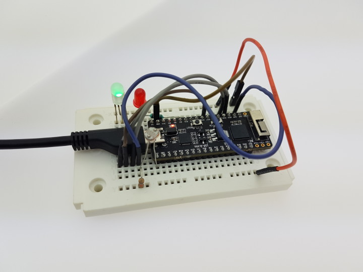
The ESP32 Pico Kit: Compact and affordable
If you already have an ESP32DevKit C, you can try out the new software straight away. There is however an alternative board that’s even more compact called the ESP32 Pico Kit, which we are also currently featuring in the Elektor ESP32 Design contest. This smaller board takes up less space on the plugboard so that any additional components can be added more easily.The same sketch was loaded 1: 1 to the new board, I couldn’t find any changes that would be required. It was only necessary to identify the corresponding pin header positions and link them out to the breadboard. Instead of pin 12, I connected the red test LED to pin 15 (and changed the code accordingly). One other change is necessary following a power supply outage: now you need to press the EN button, otherwise the program does not start.
During operation, the regular pinging activity causes a brief interruption of the cyclic LED dimming process. More information on this can be found at the end of the last episode. I carried out some trials over a complete day; during that time I periodically shut down the Wi-Fi network to simulate a dropout. On my AllThingsTalk website I have organized the sampled and published sensor values as a bar chart. In the screenshot at the beginning of the article, you can see how it slowly became dark during the afternoon in my ‘home office’. When I turned on the room light at around 6:00 pm, a small peak in the measured brightness was measured.
Stay tuned for the next installment!
Read full article
Hide full article
Discussion (0 comments)