
Understanding the Neurons in Neural Networks (Part 4): Embedded Neurons
on
With our neural network fully functional on PCs and laptops, we can be confident in our multilayer perceptron implementation. Many applications require the low power capability and minimal latency that a microcontroller offers. Others simply do not want to share their private data with third-party cloud AI services. Here we make our neural network "Arduino ready" and move our traffic light classification code to the world of embedded systems.
Embedded MCU Application
Tools and platforms for machine learning (ML) seem to be sprouting up like mushrooms. No matter how complex your task or the size of your dataset, there is a cloud service that can handle it. However, there are many cases where a cloud-based ML implementation is unsuitable. If you are handling sensitive or personal data, you may not want to transfer it via the Internet to have it analyzed by an ML tool. Another example is automotive or other real-time embedded applications. Such systems require an immediate decision so the latency of an Internet connection, or the potential for having no connection at all, demands a local ML solution. This is also known as “ML at the edge” [1].
Operating a neural network at the edge means that even simple microcontrollers can execute ML algorithms. However, due to the processor demands required for training, the network is often trained in the cloud or on a powerful PC. The resultant weights are then downloaded to the microcontroller for Internet-free, low-latency operation.
This final article of the series ports our multilayer perceptron (MLP) neural network to an Arduino. Coupled with an RGB sensor, we teach it to classify the traffic light colors as we did in Processing on your PC or laptop. Using a 32-bit Arduino (DUE or M0 Pro), we can undertake the learning phase on the microcontroller. However, we will see that it is quite slow. Thus we will also partition the task so that the network is trained using a PC's performance, then executed in the low-latency, low-power environment of an embedded microcontroller application.
Selecting a Sensor
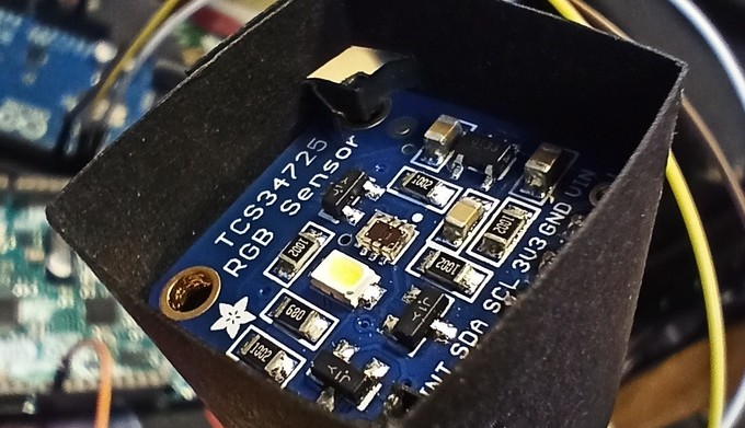
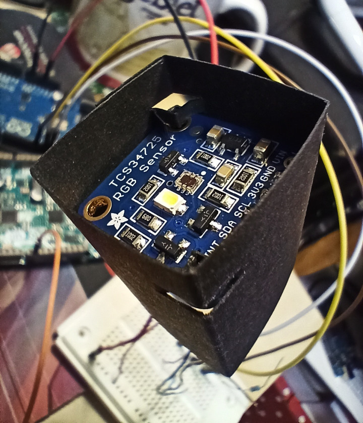
To recognize the traffic lights’ colors, the Arduino will require a suitable sensor as an input. The TCS34725 is a suitable RGB sensing solution, available ready-to-use from Adafruit in a 2 × 2 cm (0.8” × 0.8”) format PCB [2]. It allows us to acquire RGB data as we did previously with the camera and apply it to the same MLP configuration used in the previous PC-based examples. The board is suitable for use with both 5-V and 3.3-V Arduino’s, and its sensor data is acquired using the I2C, which requires the Wire library.
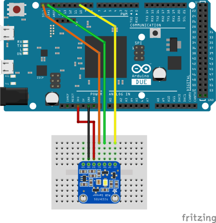
To ensure consistent lighting of the sample to be analyzed, the board also includes a white LED controlled using an Arduino digital output. Pin 10 has been selected for this purpose (Figure 1). Thankfully, the board is supported by a well-constructed library, so getting up and running is simple and straightforward. As before, we will be using the code from the GitHub repository prepared for this series of articles [3].
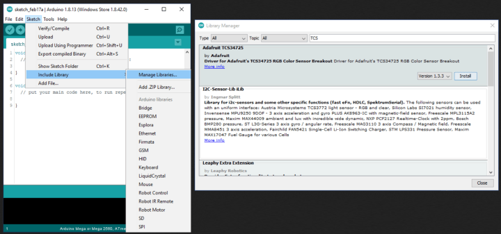
Before running any code, we must install the library for the RGB sensor. Thankfully this should also be easy as it is accessible through the Library Manager within the Arduino IDE. From the menu bar, simply select Sketch -> Include Library -> Manage Libraries… and then enter “tcs” in the Library Manager’s search box. The “Adafruit TCS34725” library should appear. Simply click “Install” to install it (Figure 2). Should there be difficulties, the source code and header file can be downloaded from the Adafruit GitHub repository [4] and added to the projects manually.
To ensure that the sensor works and provide a method to acquire the RGB values we need to train the ML, we will start with the sketch arduino/tcsrgbsensor/tcsrgbsensor.ino. After initializing the RGB sensor, the code turns on the LED and starts reporting the RGB values via the Serial output (Figure 3).
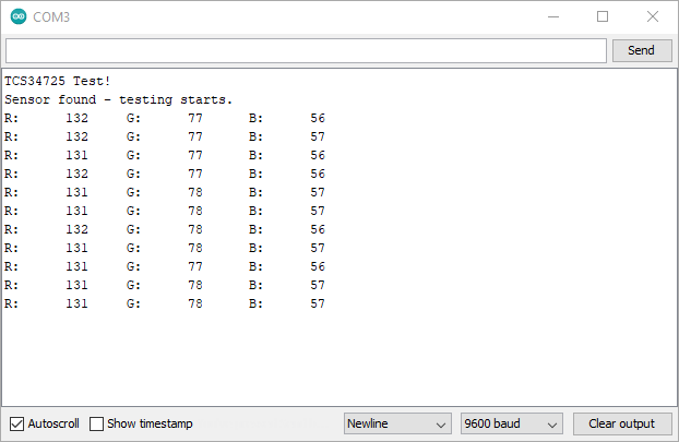
Open Tools -> Serial Monitor to view them. The baud rate setting is 9600. To improve the quality of the readings and reduce the impact of other light sources, constructing a shield around the sensor board is worthwhile. A strip of black cardboard some 3 cm high and 10 cm long is ideal (Figure 4). The shield also ensures that the traffic lights’ image can be held at a consistent distance from the RGB sensor.
With the RGB sensor delivering reliable results, we can now acquire its assessment of the red, amber, and green colors using our printed-out traffic light image (from trafficlight/resources). The results obtained by the author are shown in Table 1.
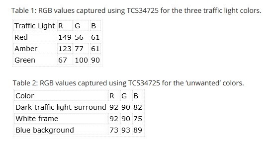
Table 2: RGB values captured using TCS34725 for the ‘unwanted’ colors.
An MLP Library for Arduino
With the RGB values determined, we now need the neural network implementation for the Arduino platform. Because Processing uses Java, we cannot simply take the Neural class code and add it to an Arduino project. Thus the Java Neural class was modified slightly to turn it into a C++ class. In the Arduino world, such reusable code objects can be turned into ‘libraries.’ These consist of a C++ class and an additional file for highlighting the class’s keywords. Should you wish to write your own library or better understand how C++ classes work on Arduino, there is an excellent tutorial on the Arduino website [5].
The code for our Neural library can be found in arduino/neural. The following Arduino projects simply include the Neural class source code in the sketch to keep things simple. The neural.h header file also needs to be added to the folder where the project is saved.
Using the Neural class on an Arduino is mostly the same as using it in Processing. Creating our network object as a global variable is slightly different and is undertaken as follows:
Neural network;
To construct the object with the desired number of input, hidden, and output nodes, we enter the following:
network = new Neural(3,6,4);
The basic configuration of the bias values and learning rate are then coded as previously in Processing:
network.setLearningRate(0.5);
network.setBiasInputToHidden(0.35);
network.setBiasHiddenToOutput(0.60);
From here, we can continue to use the methods as we used them previously in Processing.
Detecting Traffic Light Colors with Arduino
Now we can start exploring the MLP on the Arduino. The sketch /arduino/tlight_detect/tlight_detect.ino follows the same structure as the Processing project tlight_detect.pde. The neural network (3/6/4) is configured at line 40 onwards, and it is trained with the RGB data in a loop from line 51. Before executing the code, the RGB values for ‘Red,’ ‘Amber,’ and ’Green’ acquired previously need to be entered at line 56 onwards:
teachRed(220, 56, 8);
teachAmber(216, 130, 11);
teachGreen(123, 150, 128);
Upload the code and open the Serial Monitor to view the output (Figure 5). As before, the baud setting should be 9600. The project checks that the RGB sensor is functional before turning off the white LED during learning. With the MLP configured, it then runs through the learning cycle 30,000 times, improving its ability to classify each of the three colors each time.
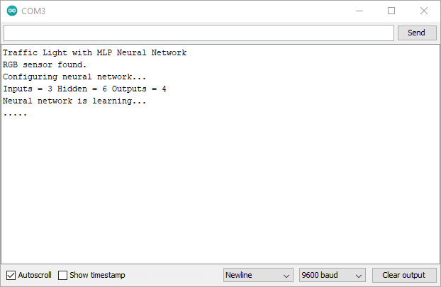
To provide some feedback during learning, a dot is output every 1,000 loop cycles (3,000 learning epochs). Compared to the PC, learning is a slow process. Each call to a learn function (learnRed(), etc.) requires around 5.55 ms to complete. Learning all three colors requires around 8.5 minutes on an Arduino M0 Pro using a SAMD21 microcontroller. If you wish to examine your platform's execution time, tick the ‘Show Timestamp’ box in the Serial Monitor and replace line 66 with:
Serial.println(".");
This adds the carriage return character and ensures a timestamp is generated for each ‘.’ character output.
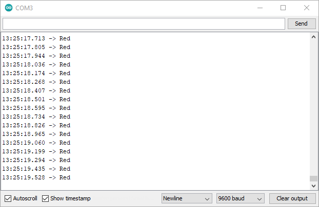
Once learning is complete, the Arduino jumps immediately into showing off its new skill. Whenever a traffic light color is detected, it is output to the Serial Monitor (Figure 6). During the author’s experimentation, the neural network also detected the color ‘Amber’ even when nothing was held in front of the sensor. Although this seemed to be related to ambient lighting, it highlights a weakness in the implementation.
To improve the code, we can teach the MLP ‘Other’ colors as we did previously in Processing. This can also be used to repress the ‘Amber’ classification when no image is present. The tcsrgbsensor.ino sketch can be used to acquire the sensor’s readings for the traffic light surround, frame, and image background. These can then be input into lines 60 onward in the tlight_detect.ino sketch in the teachOther() function calls.
The values shown in Table 2 were attained and tested with the tlight_detect.ino sketch. The classification improved, but the false classification of no image as ‘Amber’ was not totally resolved. As always, there is room for improvement!
Supercharged Learning
If you added learning the ‘Other’ colors to the Arduino sketch, you will have waited around 18 minutes for an M0 Pro to learn the desired classifications. This definitely leaves us some room for optimization of the process. Since we have a powerful PC that can calculate the weights in under a second, it would make sense to do the learning there, then transfer the results to the Arduino. With these weights, we also have a means to program multiple microcontrollers with the same ‘knowledge’. Providing the RGB sensors all function similarly with respect to our input, each microcontroller should correctly classify the traffic light image. So, this is what we will undertake next.
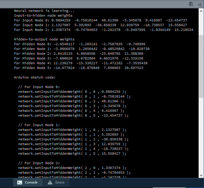
We return briefly to Processing to open the project /arduino/learnfast/learnfast.pde. The entire application runs in the setup() function. The neural network is configured with the same input, hidden, and output nodes used on the Arduino board (3/6/4). In the learning loop (line 36), the values used are those acquired from the Arduino using the RGB sensor and the tcsrgbsensor.ino sketch. When the code is run, it outputs text to its console. The last section contains the code that configures all the input-to-hidden and hidden-to-output weights (Figure 7). Simply copy the code generated starting at // For Input Node =0 until the end of the text output.
The output of the text console can then be pasted into tlight_weights.ino.
Back in the Arduino IDE we can now open the /arduino/tlight_weights/tlight_weights.ino sketch. This is the same as the tlight_detect.ino sketch but, instead of teaching the neural network, the weights are preprogrammed. This happens at line 51 with the function importWeights(). Simply paste the code from the learnfast.pde output into the importWeights() function at line 86 in tlight_weights.ino. Program the Arduino board, and it should accurately detect the traffic light colors as before.
In fact, now that we have this supercharged learning process, we can even program the same tlight_weights.ino sketch into an Arduino UNO. Simply hook up the RGB sensor to the board, open the Serial Monitor, and it will function just as accurately as it did on an Arduino M0 Pro or DUE. For comparison, you can monitor digital pin 9 to see how long it takes for the calculateOutput() method to perform the calculations.
What Next? More Embedded Systems?
So, where do we go from here? Well, we have a functional MLP neural network that works on both a PC and a microcontroller. We also have a supercharged learning process to generate the weights needed in microcontroller applications. You can try and apply this MLP to other tasks that are too difficult to resolve using if-else statements and fixed limits. It may even be possible to implement a simple voice recognition project to recognize a few words. You could also explore the following:
- The Neural class uses the data type double. Can it be sped up using float and still maintain accuracy? How much faster can it run?
- The sigmoid function uses the exp() math function, calculating the exponential raised to the argument passed. Could the activation function be simplified using an approximation and still deliver accurate classification?
- If you wanted to attempt voice recognition, how would you prepare a voice sample to present it to this MLP implementation?
- How about some significant changes? How would you implement a second layer of hidden nodes? Can you implement a different activation function?
In this series of articles, we’ve covered a lot of ground. We scratched the surface of the early artificial neuron research. From there, we examined how MLPs use backpropagation to learn and investigated its operation using the powerful processing available on a PC. We then ported the MLP to a microcontroller as an example of edge ML. Should you choose to develop these examples further, feel free to share your results with us here at Elektor.
Better Farming
Farming has always relied on nature and the seasons to determine the best time to reap and sow. Tradition had always dictated the optimal date to plant their crop to benefit from the monsoon season. However, with changing weather patterns, crop yields have suffered. All this is changing thanks to AI. Indian farmers participating in a pilot project planted their groundnut crop in late June, three weeks later than normal. The Microsoft Cortana Intelligence Suite provided this guidance. Using historical climate data, the recommendations the farmers received led to a 30% average higher yield [6].

Questions About Embedded Neurons?
Do you have questions or comments about embedded neurons, embedded applications, or this this article series? Then email the author at stuart.cording@elektor.com.
Discussion (0 comments)