
PiKVM: Raspberry Pi as a KVM Remote Control
on
KVM stands for keyboard, video, mouse, and whoever has access to it can remotely control a computer. Using the clever PiKVM software and a Raspberry Pi 4, you can inexpensively control a PC and other devices via the Internet without having to install software on the remotely controlled computer. PiKVM also enables the provision of virtual disks, so that a computer can not only be controlled and maintained remotely, but a complete reinstallation is possible.
During the pandemic, I received information that my parents still had computers running Windows 7 (some were even Windows XP) at their house. Because of the security gaps, which can no longer be fixed, these computers urgently needed to be updated. Unfortunately, an update was not enough for these machines. They required a complete reinstallation, but driving there was not an option, because of the pandemic and more than eight hours of driving time.
Anyone who has ever tried to guide someone through dozens of installation steps with a mixture of phone call and video chat can easily imagine that such a thing is not a good idea for an operating system installation and data backup. Remote access is what’s needed. And that’s exactly what is made possible with a Raspberry Pi as a KVM remote control.
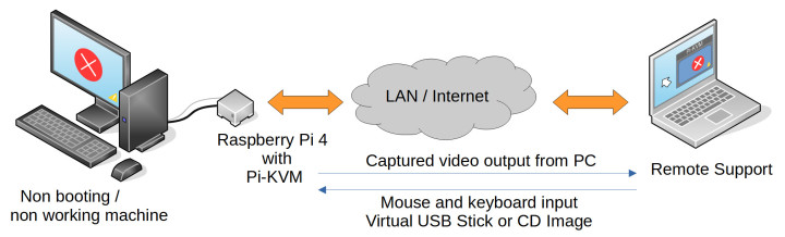
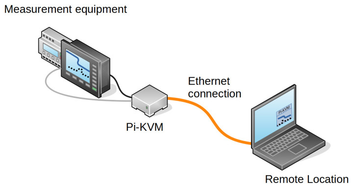
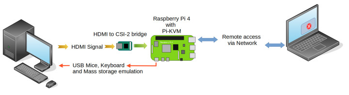
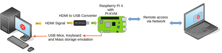
At this point in the text, you can replace parents with customers, computers with machine controls, and new installation with error analysis. A pair of eyes with which one can look at a system remotely, independent of hardware, makes it possible to avoid long trips to a site. It is also possible to remotely operate devices and measuring instruments that were never intended for this purpose by the manufacturer. Figure 1 illustrates the use of PiKVM for remote control of a PC. A machine could be remotely maintained as shown in Figure 2.
The PiKVM Alternative
There is remote maintenance software, isn’t there? If you are using a Raspberry Pi or a PC, you will surely have used a tool like VNC, AnyDesk or TeamViewer. Besides these, there are quite a few other solutions for remote maintenance and control. All these solutions are inexpensive or even free of charge for the private user. To help someone set up new software or create social media posts, something like this is a quick and easy solution. However, these helpers all require a running operating system with an Internet connection.
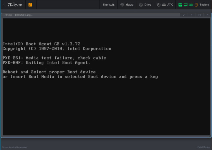
But what if the computer no longer boots or can no longer establish a network connection? Or if the operating system has to be reinstalled? That’s the point at which someone with appropriate expertise needs to be on site to get the operating system to boot again and establish a network or Internet connection. This also applies to reinstalling an operating system. Figure 3 shows the BIOS message of a PC that could not find bootable media.
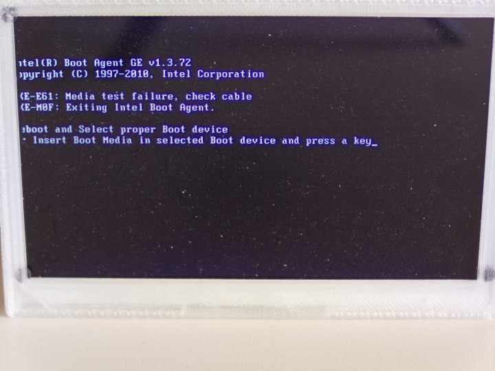
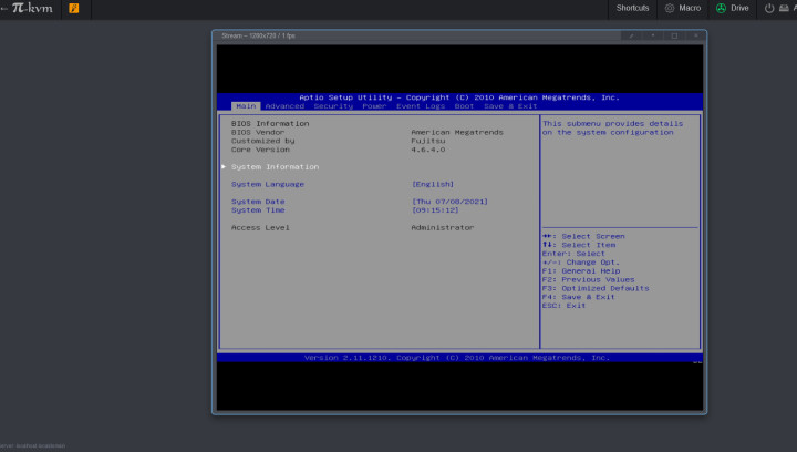
PiKVM works independently of the computer to be controlled and transmits the video image that the graphics card outputs via the network to a second system that only needs to run an HTML5-capable web browser. There, not only the image output of the remotely controlled computer can then be displayed; the mouse movement and keyboard inputs are also returned to the computer to be controlled. This allows you to remotely control the computer as if you were sitting in front of the computer’s screen, mouse and keyboard. Figure 4 shows the BIOS message of the PC now comfortably in the browser of a remote computer. Access to the BIOS (as shown in Figure 5) can also be conveniently controlled via a remote browser, so it is not absolutely necessary to be near the PC.
Virtual Disks
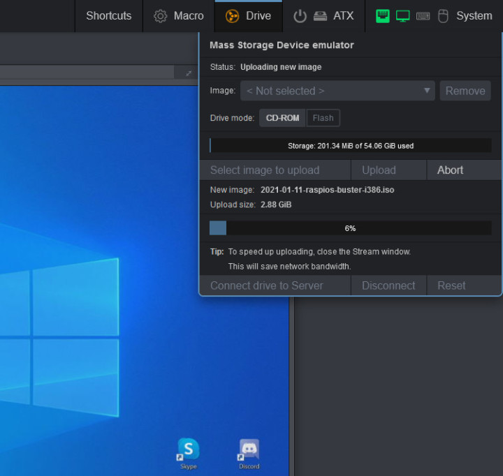
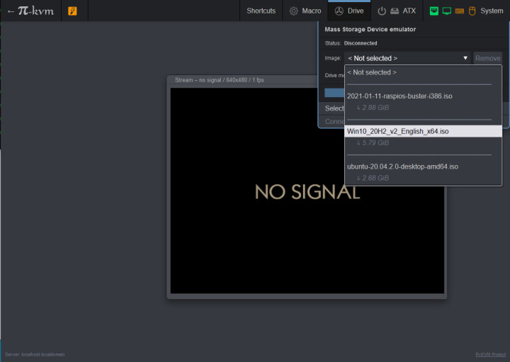
Something that gets complicated over longer distances (usually 2 m is enough) is the insertion of USB bootsticks, or rotating data media such as DVD or CD. You could send a bootstick to the PC to be controlled remotely and hope that someone onsite will insert it correctly. PiKVM offers the option of virtual disks (i.e., it can emulate a USB stick or a USB-CD-ROM drive). To do this, you can simply upload and mount the appropriate disk image via a browser. Figure 6 shows the virtual disk menu. Currently, CD emulation is limited to ISO files, so they must not be larger than 2 GB. For ISO files larger than 2 GB (Figure 7), hybrid ISOs must be available (i.e., those that could also be written to a USB stick). These can then be used with the Flash emulation type and appear as USB mass storage.
An Affordable, Open-Source Solution
Doesn’t something like PiKVM already exist? The functions provided by a PiKVM are also offered by other devices from other manufacturers, but usually much more expensive than the PiKVM solution and with closed-source firmware. With these devices some comfort functions are then also subject to an extra charge. The Pi-KVM comes as an open-source project and can be assembled with common hardware. In the end, you have to budget about €100 for the DIY solution.
There are two ways to build a PiKVM, one with an HDMI-CSI bridge and one with a USB-HDMI dongle. Figure 8 and Figure 9 show the data flow through the Raspberry Pi 4 with the respective solution. At this point, we would like to present the required components and give a few hints about how to build them.
The Necessary Hardware for PiKVM
The hardware needed for the PiKVM is quite simple:
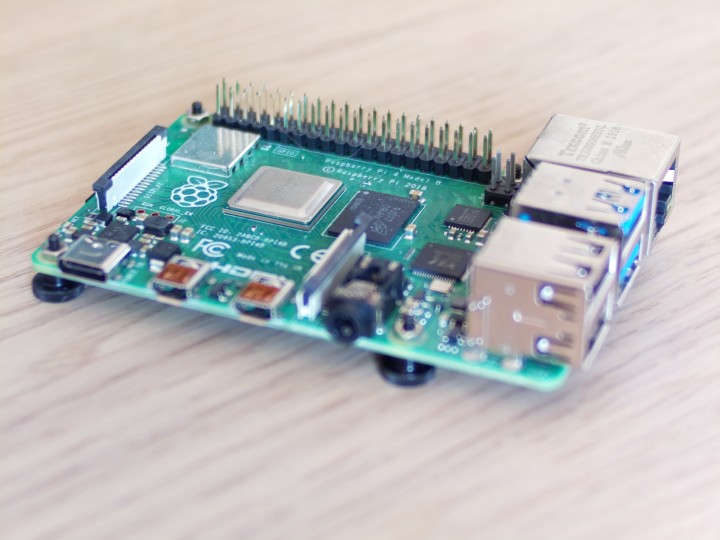
- A Raspberry Pi Model 4 (2 GB RAM or more) (Figure 10)
- One Micro SD card (16 GB recommended)
- One USB power supply (5 V/3 A)
- Optional housing
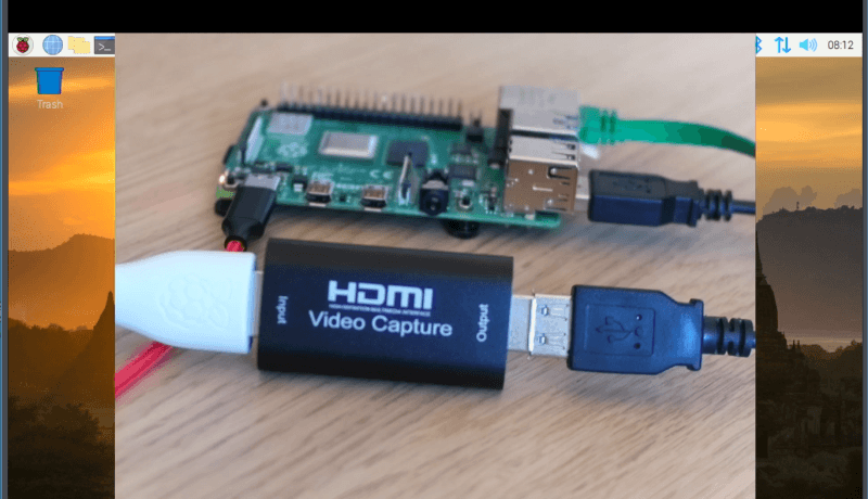
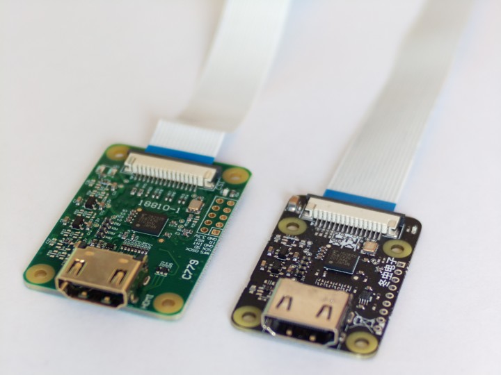
- HDMI-to-CSI Bridge or USB HDMI Capture Dongle (Figure 11)
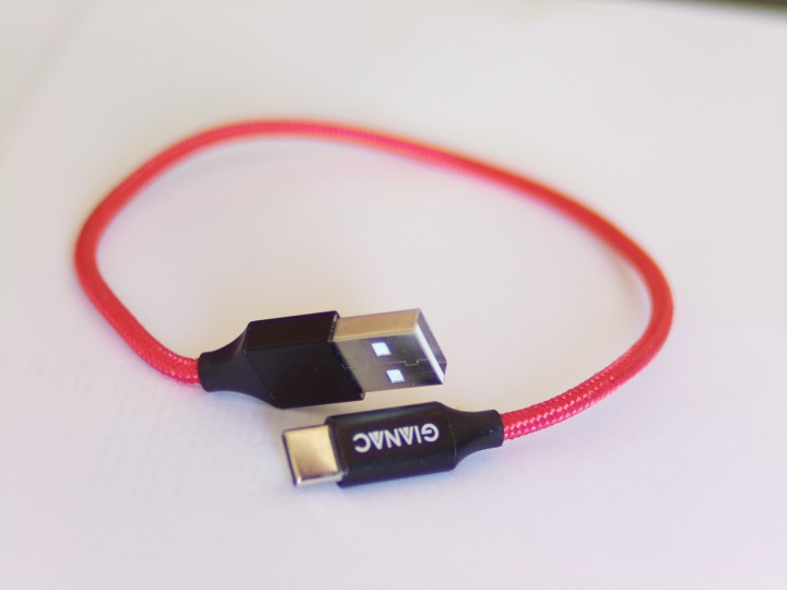
- A USB Y-cable (Figure 12 and Figure 13)
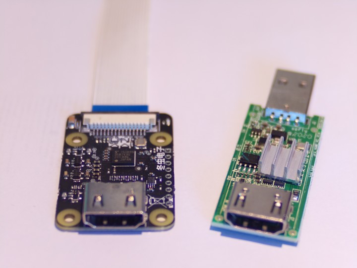
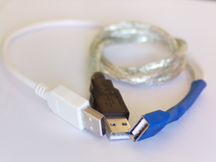
While the first three components should be available or easy to get for most readers, the last three are a bit more difficult to get. For the HDMI-to-CSI bridge (Figure 14 shows two available variants), on the other hand, you have to search a bit for a European source or resort to one from the Far East. A USB HDMI capture dongle can be ordered for a few Euros from relevant mail-order companies. Even though the price of these dongles may be tempting, they have some limitations in terms of stability or supported resolutions. The HDMI-to-CSI bridge is the more stable and compatible choice.
For the connection between the Raspberry Pi 4 and the computer to be controlled, the USB-C port of the Raspberry Pi 4 is used in USB OTG mode. This allows the Raspberry Pi 4 to behave like a keyboard, mouse or mass storage device towards a PC. For this, the Raspberry Pi 4 is connected to the computer with a USB-A to USB-C cable and would also be supplied with power via this. Since 3 A at 5 V is required here, stable operation cannot be guaranteed, so an additional power must be provided by a power supply unit.
Since the USB-C port is used in OTG mode, you could feed 5 V into the Raspberry Pi 4 via the 40-pin header. However, these 5 V would then also supply power to the computer connected to the USB-C port. This is something that quite a few computers do not like and acknowledge with malfunctions. One solution is to use a Y-cable that splits the data and the power supply.
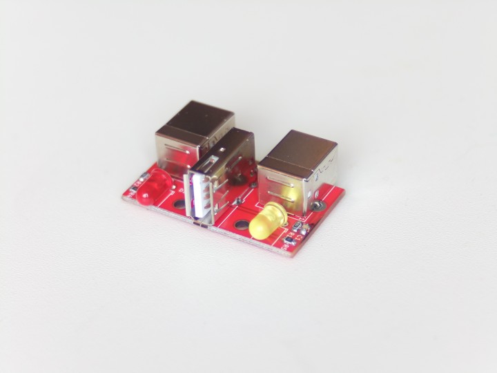
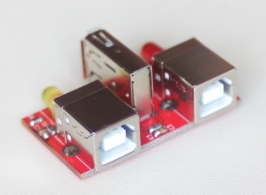
So that two USB cables do not have to be soldered together to fit, the Elektor Lab has routed a small circuit board (Figure 15). Two USB-B sockets (Figure 16) allow one connection to a power supply and one connection to a computer without feeding 5 V backwards. Both sockets have in common that a LED signals the presence of the 5 V bus voltage. The board is available as a KiCAD project and can be downloaded from the Elektor GitHub repository. However, the board has not yet been tested extensively, so rebuild at your own risk. You can find a component list and the circuit diagram at the end of the article.
Discussion (2 comments)