
Small Circuits Revival (35): Phaser
on
Phaser (3)
idea: Elex Team
Our phaser needs a symmetrical power supply of ±9V. Note: With ± (plus) we do not mean "about 9 V," but "plus 9 V and -9 V"! When you consider that this circuit has six (6) LEDs, it will not surprise you that the power consumption is not really small: on average about 60 mA (with the lion's share provided by the positive part of the power supply). And that means that power from two 9V batteries (6LR22) may be possible, but given the short life of the batteries, it is not a really good idea. A small symmetrical power supply of ±9V is urgently preferable!
About the adjustment, we can be brief: with trimpot P1, you can set the desired oscillator frequency once. With potentiometer P2, you control the output level. And with P3, you set the proportion of the "phased" signal in the output signal.
Let's come back to the LEDs for a moment. Each LED has to be mounted opposite the corresponding LDR. Take a look at the fragment of the complete schematic below.
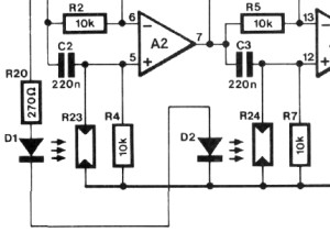
Clearly, no ambient light should fall on the LDRs, so the phaser must be housed in a light-tight housing. In addition, you should (try to) use black cardboard (or plastic tubes) to ensure that each LED can only illuminate its "own" LDR.
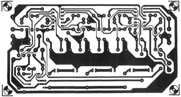
The phaser can be mounted on a hole PCB with a bit of dexterity. When the circuit was first published (just over 30 years ago!), a PCB was designed for it; but you will understand that it is no longer available. Also, the original films of that PCB (taped with red tape on transparent raster foil — that was handcrafted back then, no computer was used!) no longer exist. Nevertheless, you can download a full-size copy of that layout (plus component layout) below. That copy probably isn't good enough to be used to expose a PCB to UV light, but it can likely serve as an example for your own PCB layout.
Discussion (0 comments)