Arduino is the electronic Swiss Army knife of simple and creative programming. There remains the question of parts, soldering, wires…. that some feel is an obstacle. If you don’t want to jump into the Arduino waters without a lifejacket, you’ll want a good introductory kit. And here’s one that is affordable and offers a good selection of sensors and controls with easy connection to the Arduino.
Almost no-one is afraid of Arduino; in just a few years it’s become the embedded microcontroller that (almost) anyone can master. The popularity of this platform is explained by the convenience of the free programing environment (IDE) and by the dynamic community of users. Creative people who know little or nothing technical, and don’t really wish to know much, can attain a set goal or realise this or that function – Arduino is the electronic Swiss Army knife of simple and creative DIY programming.
There remains the question of parts, soldering, wires…. that some feel is an obstacle.
If you don’t want to jump into the Arduino waters without a lifejacket, you’ll want a good introductory kit, such as the one I presented a few weeks ago: mCookie. Its high-end specifications (WiFi, Bluetooth. Real Time Clock etc), its high quality design and finish, smart interconnections via magnetised modules, place it in a price bracket that is out of reach for many buyers, especially if you’re just starting out..
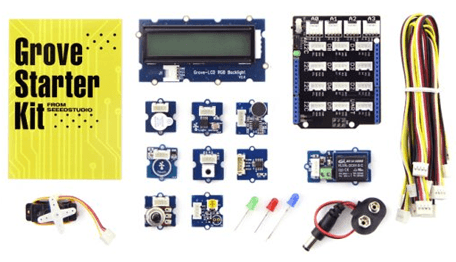
Some of the kit contents.Happily, there are less ambitious and cheaper alternatives, like the Grove Starter kit for Arduino from seeedstudio that you will also find in the Elektor E-shop.
No soldering iron, no breadboards
The principle of such a kit consists in bringing together for the novice a collection of universal small sensor and control modules, and to enable their easy connexion to an Arduino UNO board. No need for soldering iron or breadboards, as everything passes to and from the Arduino via a signal distribution card (the Arduino itself is not supplied in the kit) and by a set of cables which solidly connect the modules. Here there are ten modules and the same number of ribbon cables (20cm / 8 inches each). When you realise that for each module you’d need 3 or more wires if cabling them by hand, the benefits of this kit become apparent: no spaghetti of wires which risk coming off at the slightest movement!
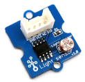
The circuit board of each module is around 2x2 cm (3/4 inch square) and has a connector by which you connect it (by a cable with a 4-way female plug at each end) to the distribution board. This is called a “Base Shield” and is equipped with male pins exactly matching the Arduino Uno. You’ve probably already seen elsewhere that the principle of Arduino extension cards, called “Shields”, is to connect the input-output connectors of your Arduino by means of male pins on the solder side of the “Base shield”.
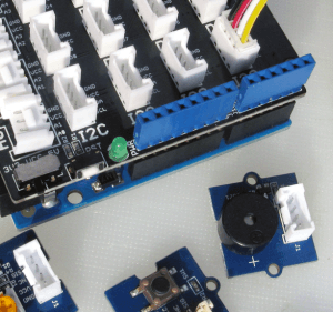
Base shield connected to the Arduino. Next to it,
the piezo resonator and the pushbuttonOn the other side on either edge of the “Base Shield” you find the corresponding female connectors (blue) which in turn allow you to stack one or more other Shields.
The rest of this board is occupied by the bases for the cable connectors. We’ll return to them in a moment. If you have a version of the Arduino prior to the R3, you’ll find that two sockets are missing in two places, so that 4 pins of the Base Shield are in the air. In fact, this does not matter.
The other modules are :
A backlit 16x2 LCD display;
A 35 V / 1 A Relay (to control heavier loads, for example a small motor, a switch, or a more powerful relay)
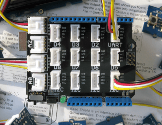
According to their function, the modules are connected to a different category of connectors on the Base shield board: A0 to A3 for analog modules like the angle sensor (potentiomenter) or the sound sensor (microphone). D2 to D8 are for logical modules (Controlling on or off states) like the relay, the LED or the push button. Logical port 1 is labelled UART, as it’s the default serial interface of the Arduino. Logical D3, D5 and D6 can be used for pulse width modulation (PWM); this permits, with a logical (on or off) port, to achieve proportional control, for example to control motor speed or the intensity of a LED. .
The LCD display is connected to the connector marked “I2C”. Note here that it’s actually the backlighting of the display that is in color (red, green or blue) not the text or the pixels themselves which are monochrome.
If you get the connector wrong on the Base Shield, the sketch will not work, but apart from that nothing terrible will happen. That’s one of the advantages of this type of starter kit, compared to working on a breadboard.
All the small boards (like the relay module here, for example) have eyelets and notches by which they can be attached to a board, with or without spacers.
Aside from the green LED power indicator, the Base shield has no active components, but it has a reset button for the Arduino and a switch for the choice of power voltage (3.3 V or 5 V).
The kit is presented in a solid translucent plastic box with storage compartments and a manual which describes the function of each module, well enough for the beginner to get out of trouble, and offers several small applications. For these you can just download the corresponding sketches (programs) from the seeed website and load them into the Arduino. This procedure is described in detail on the seeed site. For example, here is a sketch which lets you turn on and off a LED with the touch switch and the LED module. You can’t get much simpler than this!
const int TouchPin=9;
const int ledPin=12;
void setup() {
pinMode(TouchPin,INPUT);
pinMode(ledPin,OUTPUT);
}

void loop() {
int sensorValue = digitalRead(TouchPin);
if(sensorValue==1)
{
digitalWrite(ledPin,HIGH);
}
else
{
digitalWrite(ledPin,LOW);
}
}
Many programmers who are starting out don’t really want to improve their knowledge of electronics, but anyone who wants to know exactly what’s on these modules has only to download the schematics (note: .ZIP file). They don’t have any explanations, but if you are a little curious they will allow you not only to understand what you are doing, but once you have familiarised yourself with the subject, to modify one or another module to suit your needs. And once you’ve dipped your toe in the waters, you’ll start a wonderful adventure of electronic discovery. That’s the worst we wish you!
It is interesting to note that these Grove modules not only offer an easy start to the world of programming for sensors, but also that they are compatible with other interface boards apart from the Arduino base shield. They are available for more powerful boards than the Arduino, like the Raspberry Pi, Beaglebone, Mbed etc, with which you can re use them if you pursue your quest into the Internet of Objects.
Elektor Magazine has been one of the leading sources of information on electronics for engineers, designers, start-ups and companies for 65 years. Our magazine is powered by an active community of electronics engineers – from students to professionals – who are passionate about designing and sharing innovative ideas.
For them, we publish hundreds of items a year, in formats such as articles, videos, webinars, and other learning formats. Our mission is to share knowledge in every possible way and inspire readers with the latest developments within the electrical engineering sector.
Thank you for your vote!
Leave further comments in the fields below.
Thank you for your vote!
If you wish to leave a comment with your rating, please first use the login below. If not, just close this window.


 According to their function, the modules are connected to a different category of connectors on the Base shield board: A0 to A3 for analog modules like the angle sensor (potentiomenter) or the sound sensor (microphone). D2 to D8 are for logical modules (Controlling on or off states) like the relay, the LED or the push button. Logical port 1 is labelled UART, as it’s the default serial interface of the Arduino. Logical D3, D5 and D6 can be used for pulse width modulation (PWM); this permits, with a logical (on or off) port, to achieve proportional control, for example to control motor speed or the intensity of a LED. .
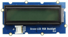
 The LCD display is connected to the connector marked “I2C”. Note here that it’s actually the backlighting of the display that is in color (red, green or blue) not the text or the pixels themselves which are monochrome.
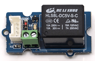
 The kit is presented in a solid translucent plastic box with storage compartments and a manual which describes the function of each module, well enough for the beginner to get out of trouble, and offers several small applications. For these you can just download the corresponding sketches (programs) from the seeed website and load them into the Arduino. This procedure is described in detail on the seeed site. For example, here is a sketch which lets you turn on and off a LED with the touch switch and the LED module. You can’t get much simpler than this!
const int TouchPin=9; const int ledPin=12; void setup() { pinMode(TouchPin,INPUT); pinMode(ledPin,OUTPUT); } void loop() { int sensorValue = digitalRead(TouchPin); if(sensorValue==1) { digitalWrite(ledPin,HIGH); } else { digitalWrite(ledPin,LOW); } }
Discussion (0 comments)