The Challenger RP2040 WiFi Arduino/Micropython Compatible Microcontroller Board
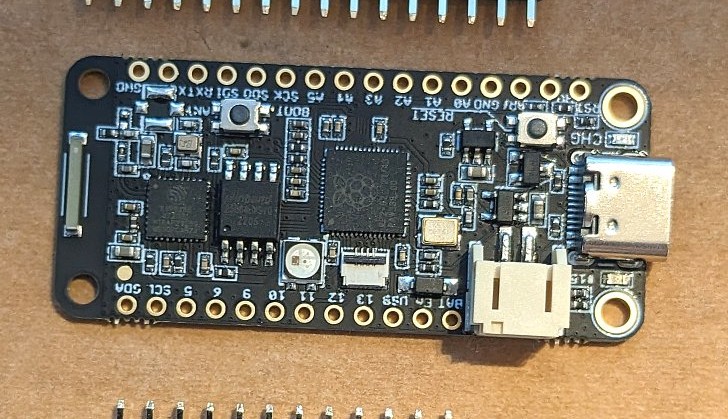
The Challenger RP2040 WiFi is a microcontroller board from iLabs. It combines a Raspberry Pi RP2040 microcontroller with an ESP8285 for Wi-Fi connectivity. The board has two LEDs, one of which is a NeoPixel, and it has a special type of I²C bus (Bi2C) using Flexible Flat Cable (FCC).
The Challenger RP2040 WiFi is a microcontroller board from iLabs, based on the Raspberry Pi RP2040, combined with an ESP8285 for Wi-Fi connectivity. As far as features go, the board has two LEDs, one of which is a NeoPixel. Furthermore, it has a special type of interconnect bus (Bi2C), which is an I²C bus, but uses a Flexible Flat Cable (FFC) with 0.5-mm-pitch connectors, making them small. The board itself is based on the Feather form factor from Adafruit. As they say, “boards of a feather flock together”, the idea of this form factor, which also standardizes GPIO layout and location, is to make it easier to swap and extend different types of microcontroller boards.
RP2040 Controller
This board uses as its main controller a Raspberry RP2040, a dual-core Cortex-M0+ device with 264 KB of SRAM, to which 8 MB of external FLASH memory has been added. The RP2040 has become very popular lately as it is a very capable microcontroller, coming at a sharp price point. Not only that, but its growing community provides us with toolchains and utilities that seamlessly integrate RP2040 based boards in the Arduino and Circuit/MicroPython community.
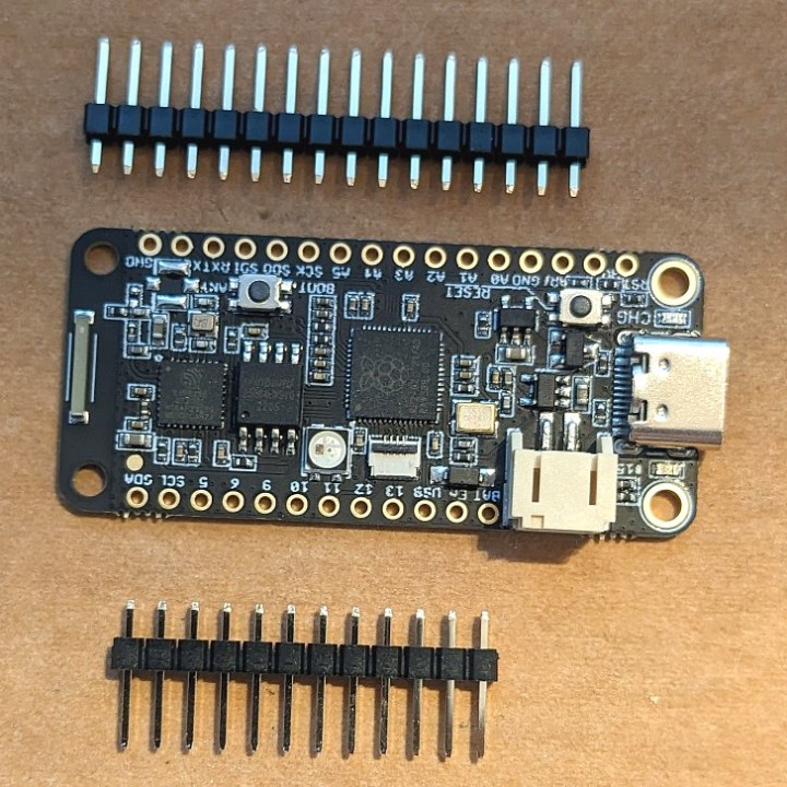
The Challenger RP2040 Wifi has a Feather form factor.
Wi-Fi by ESP8285
Wi-Fi connectivity is provided by an ESP8285, which is basically an ESP8266 with 1 MB of integrated flash memory. The communication between the ESP8285 and the RP2040 is over a serial connection. The ESP8285 has an AT command interpreter on board. This way, the controller can use a simple serial protocol to talk to the local Wi-Fi network. This can be a lot easier than having just a Wi-Fi transceiver that you need to provide with your own TCP/IP stack. The AT command interpreter pulls the Wi-Fi functionality to a higher level because it also has support for HTTP and MQTT protocols.
Subscribe
Tag alert: Subscribe to the tag RP2040 and you will receive an e-mail as soon as a new item about it is published on our website!
Onboard LEDs
The Challenger RP2040 has two LEDs on board. One is the typical ‘blinky’ LED found on most Arduino-compatible boards. The other LED is a NeoPixel and that makes it a lot more interesting. A NeoPixel is an Adafruit brand for addressable RGB LEDs. You can find these LEDs also on strips and matrices, on which each of them is individually addressable via a single-wire control protocol.
USB-C Connector
I like the USB-C connector on this board, which not only makes it a lot less fiddly than a micro-USB connector, it is also more robust and durable. The USB connector is used to program the Challenger RP2040, but can also be used to power the board. It also doubles as a charging input when a battery is connected.
Battery Connector and Charger
Surprisingly, the Challenger RP2040 WiFi has a battery charger circuit on board. You can connect a single LiPo (only) battery via a 2-mm-pitch ‘JST’ connector. This lets you use the Challenger RP2040 as a portable device. Charging only requires a USB-C cable, so any charger you have lying around will probably do.
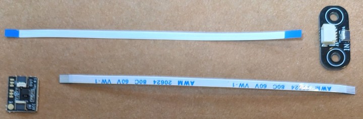
The Bi2C Bus uses small FCC connectors and "cables".
The Bi2C Bus
Traditionally, there have been a few interconnect standards available for microcontroller boards like Grove, Qwiic, etc. The Challenger RP2040 has its own ‘standard’: the Bi2C (Bus I²C) concept. Here a Flexible Flat Cable (FFC) is used instead of wires as used by the other standards. These FFC connectors can have a pitch of 0.5 mm and the flat cable is narrow as well. There is a 4-wire version with the SCL and SDA signals (and power) and a 6-wire version that adds two GPIO ports.
The kit I received for reviewing included, besides the Challenger RP2040, also two Bi2C boards: an accelerometer module and a Bi2C-to-Qwiic adapter board.
Accelerometer with Bi2C Interface
The Bi2C–ACC is a 3-axis, 16-bit accelerometer expansion module based on the MC3419 accelerometer. The chip used is optimized for cell phones and consumer-product motion sensing. It has dedicated motion sensing logic built-in which implements algorithms to support “any motion”, shake detection, flip, and tilt, among others.
The Bi2C-to-Qwiic Adapter allows you to integrate Sparkfun Qwiic as well as Adafruit Stemma peripherals in a Bi2C system (or the other way around).
Programming
Programming the Challenger RP2040 is done over USB-C and is like programming any other Raspberry Pi Pico compatible board. The device shows up on your computer as an external drive and, depending on the platform you use, you either drag-drop files on it or let the (Arduino) IDE take care of it.
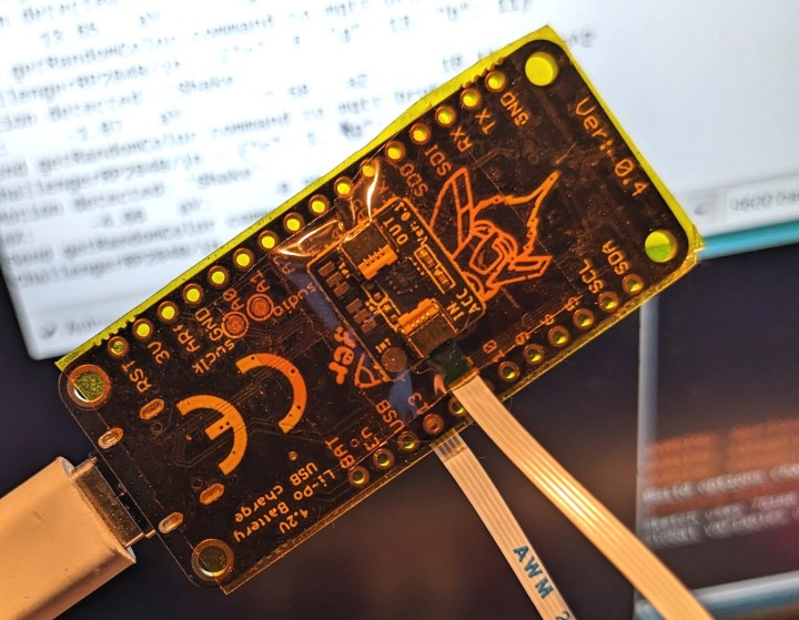
Although you can program the RP2040 using a GNU C/C++ toolchain, I think it is better to choose a platform like Arduino or MicroPython. The Challenger RP2040 with an accelerometer stuck on its back.
I first flashed the Challenger RP2040 with CircuitPython, which is based on but simpler than MicroPython. As editor, I used the nice Mu editor, which is both beginner-friendly and supports CircuitPython. The problem I quickly ran into was a lack of support for the NeoPixel LED, Wi-Fi and accelerometer. Maybe I was just looking in the wrong places, as I’m not that familiar with the CircuitPython ecosystem.
Using the Arduino IDE
Next, I tried the Arduino IDE. After installing support for Raspberry Pi Pico/RP2040 based boards, I started exploring the features of the Challenger RP2040 WiFi.
The onboard LED is handled as a standard LED in Arduino, i.e. you use pinMode to set it to output and a digitalWrite to switch it on or off. For the NeoPixel you can use the Adafruit_NeoPixel library from Adafruit.
The accelerometer is based on a Memsic MC3419 accelerometer, which requires adding a library. I like the way you can use the accelerometer to react to some higher-level motions, like ‘shake’ or ‘tilt’ instead of doing the math yourself.
AT Commands
As the Wi-Fi functionality is provided by an AT command interpreter running on the ESP8285, we need to use a Wi-Fi library with AT support. The WiFiEspAT library was especially written for this. You also need a small ‘bootstrap’ library, called ChallengerWiFi to reset the ESP8285 and get it going. The code on how to do that is provided in the example.
AT to MQTT Wrapper
Because the AT interpreter has support for MQTT, we can use a wrapper library that makes use of the specific MQTT AT commands on the ESP8285 to provide MQTT functionality for the Arduino sketch. This wrapper library is called EspATMQTT.
If you are not familiar with MQTT, this is a communication protocol mostly used for IoT projects. It allows clients to subscribe to certain events, so they get notified when an event happens, like when a temperature sensor reaches a certain threshold value, e.g. too hot or too cold. It also allows clients to send events to other devices over a central server, called the message broker. A popular message broker is Eclipse Mosquitto.
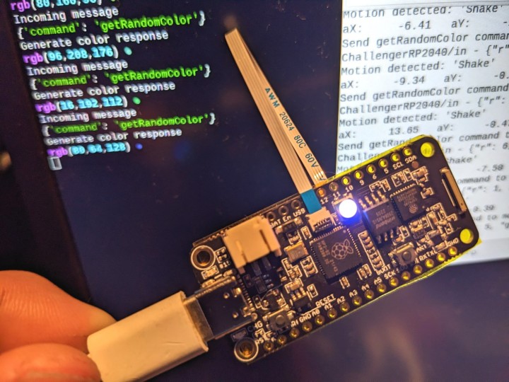
The Challenger RP2040 Wifi running the MQTT shake test app.
A Small Test Project
The proof is in the (tasting of the) pudding, so I decided to do a small project that touches most, if not all, features of the board. With an accelerometer capable of detecting shaking and having an easy way to use MQTT, I came up with the following idea:
If you shake the Challenger board, it sends (publishes) a message to an MQTT broker somewhere in the network (in my case, this is installed on a computer running Ubuntu 20.04 LTS server edition). A short Python MQTT client script running on my desktop computer subscribes to this message. Every time it receives a shake message, it sends a random color value back to the board, where it gets displayed on the NeoPixel. Each time a message is sent or received, the onboard LED blinks.
When the Challenger RP2040 arrived, I was uncertain what to expect. Although I have a lot of experience with Arduino, I never had the opportunity to use an RP2040-based board. To my surprise, it was rather easy to set up and get going.
The Challenger RP2040 WiFi is a capable board that comes in a handy Adafruit Feather form factor. I like the Bi2C interconnect, as it enables daisy-chaining and uses small cables that help to declutter the project. There exist more types of Challenger RP2040 boards. Some come with a built-in accelerometer. You may want to check these out as well.
Elektor Magazine has been one of the leading sources of information on electronics for engineers, designers, start-ups and companies for 65 years. Our magazine is powered by an active community of electronics engineers – from students to professionals – who are passionate about designing and sharing innovative ideas.
For them, we publish hundreds of items a year, in formats such as articles, videos, webinars, and other learning formats. Our mission is to share knowledge in every possible way and inspire readers with the latest developments within the electrical engineering sector.
Thank you for your vote!
Leave further comments in the fields below.
Thank you for your vote!
If you wish to leave a comment with your rating, please first use the login below. If not, just close this window.

Discussion (0 comments)