
Review: FG085 function generator kit
When soldering the rule is that flat components should be mounted first. The manual follows this and the suggested order is correct. The five electrolytic capacitors should be easy to fit providing you follow the polarity identification printed on the PCB. For the pushbuttons, hold them with your finger from the front and solder just two diagonally opposed pins. After they have all been mounted in this way you can flip the board to check their positioning and make any necessary changes without the need to desolder all six pins.

As you can see I needed to make an adjustment with pushbutton 3. Once you are happy, solder all the remaining pins. Finally the LCD module is positioned on the SIL pinheader and soldered. Now you can assemble the boards using the screws and brass standoffs in the four corners.
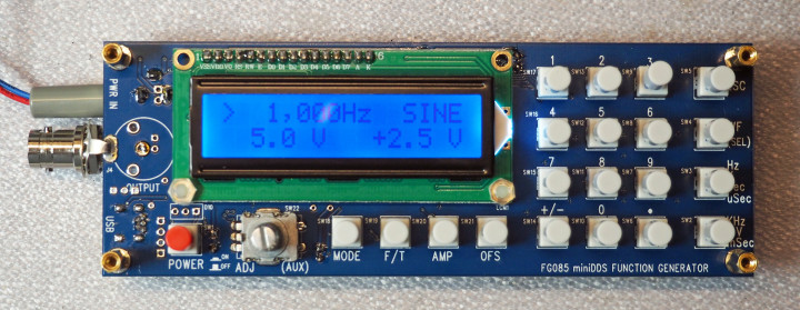
For test purposes I just loosely connected the BNC connector (when it’s finished, it mounts on the front panel). Now with a 15 V mains adapter supply connected to the power socket the moment of truth was at hand. A press of the red button and… tada! The function generator boots and after about two seconds it’s ready for use.
Now I can disconnect power and fit the BNC connector to the front panel. For this you need to first peel off its protective film.

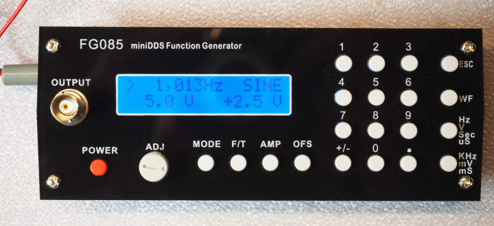
This film is made of paper and is a bit fiddly to take off. Once all traces are removed you can see the resulting neat front panel. This alone would take a lot of time and effort to produce yourself. The BNC mounting hole in the front panel is not just circular but has flats to prevent the connector rotating when the mating BNC connector is plugged in. For connecting the output signal to the BNC socket I just used some wire offcuts left over from mounting the electrolytic capacitors. The signal connects to the center pin with ground connected to the connector body.
The assembled function generator module looks really neat and is could be fitted into an enclosure using the front and rear panels supplied. It remains to see how the generated signal looks on an oscilloscope.
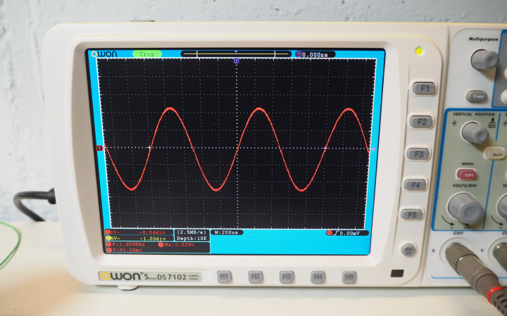
You can see the quality of the sine waveform on my LCD Scope display. There were no problems by assembly. I didn’t rush but from start to finish, including taking the photos, assembly took around two hours. It pays to be thorough and make sure there are no unintentional solder bridges between joints.
This is undoubtedly going to be a useful bit of kit for my home lab and anyone interested to explore its capabilities should study the manual and the included schematic. It’s a big advantage to have all this information available if you find it necessary to make any repairs some time in the future.
My overall conclusion is that for such a low-cost device this function generator has a lot to offer; for all its capabilities it takes up little bench space and is certainly going to be a useful addition to my home lab.
NB from Peter Aufegger: There's even a guide to produce a 3D printed housing for this unit.
As you can see I needed to make an adjustment with pushbutton 3. Once you are happy, solder all the remaining pins. Finally the LCD module is positioned on the SIL pinheader and soldered. Now you can assemble the boards using the screws and brass standoffs in the four corners.
For test purposes I just loosely connected the BNC connector (when it’s finished, it mounts on the front panel). Now with a 15 V mains adapter supply connected to the power socket the moment of truth was at hand. A press of the red button and… tada! The function generator boots and after about two seconds it’s ready for use.
Now I can disconnect power and fit the BNC connector to the front panel. For this you need to first peel off its protective film.
This film is made of paper and is a bit fiddly to take off. Once all traces are removed you can see the resulting neat front panel. This alone would take a lot of time and effort to produce yourself. The BNC mounting hole in the front panel is not just circular but has flats to prevent the connector rotating when the mating BNC connector is plugged in. For connecting the output signal to the BNC socket I just used some wire offcuts left over from mounting the electrolytic capacitors. The signal connects to the center pin with ground connected to the connector body.
The assembled function generator module looks really neat and is could be fitted into an enclosure using the front and rear panels supplied. It remains to see how the generated signal looks on an oscilloscope.
You can see the quality of the sine waveform on my LCD Scope display. There were no problems by assembly. I didn’t rush but from start to finish, including taking the photos, assembly took around two hours. It pays to be thorough and make sure there are no unintentional solder bridges between joints.
This is undoubtedly going to be a useful bit of kit for my home lab and anyone interested to explore its capabilities should study the manual and the included schematic. It’s a big advantage to have all this information available if you find it necessary to make any repairs some time in the future.
My overall conclusion is that for such a low-cost device this function generator has a lot to offer; for all its capabilities it takes up little bench space and is certainly going to be a useful addition to my home lab.
NB from Peter Aufegger: There's even a guide to produce a 3D printed housing for this unit.
Read full article
Hide full article
Discussion (0 comments)