
Review: Bench-top Power Supply PeakTech PSU 6225A
Setting the output voltage…
…is, let’s say original, at least to me as I had not yet encountered this way of doing things on a lab PSU. It is simple enough and involves a single rotary encoder with integrated pushbutton (my favourite control). Spin the knob to change the voltage in volts (coarse), press it to make the knob adjust the decivolts (fine). Press it once more to switch back to volts. The lower digit of the 2-digit value that is adjusted blinks as long as the value is changing. When the knob is idle for about one second, the display becomes fixed.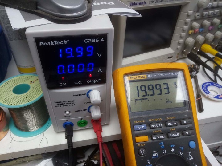
The current limiter value is set in a similar manner: hundreds of mA (coarse) or milliamps (fine).
Volts or decivolts?
The catch here is that you do not know beforehand what the knob will control: volts or decivolts (hundreds of mA or mA). There is no indicator. This can lead to unwanted situations when for instance you want to increase the supply voltage of the circuit under test by say 400 mV but because the encoder is set to volts, you increase the voltage by 4 volts instead. Not quite the same thing...
For precision adjustments the rotary encoder seems to be lacking a bit of accuracy in the decivolts range. Single clicks to the left (decrease) or right (increase) not always result in the expected value and increases may become decreases and vice versa. This behaviour was not observed in the volts and mA range.
Read full article
Hide full article
Discussion (0 comments)