
Review: PicoScope 2208B-MSO USB Oscilloscope
The software installation went smoothly on my Lenovo U410 Ideapad ultrabook-style laptop. For connoisseurs: that’s an Intel i7 core laptop with 24 GB SSD and 1 TB HD, running Windows 7 Home Premium (no 10 for me thank you).
When connected to the PC’s USB port the 2208B MSO powers up and makes itself known with a light, rapid series of clicks from what I guess are reed relays in the box, passing a reset & verification procedure. The same little music is heard when you press the Auto Setup button in the control display to enable the scope to figure out a set of initial, global, get-u-going, setting to best display your waveform. I admit to having used that Auto Setup button a lot when I was confused with my beginner’s settings to grapple with complex signals, especially the trigger and delay stuff. It’s a much advanced version of pressing Beam Find on a ‘scope some 60 years older than the Pico.
Coming from the CRT era I was delighted to read in the Getting Started manual that your first test on the up and running Picoscope should be to touch the probe tip and view the 50 Hz (or 60 Hz) waveform known as “hum”! Hey presto:
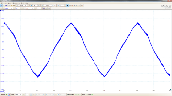
Notice the uncluttered screen with maximum size given to the measured signal. There’s lessons to be learned there, Microsoft people!
As an exercise in working with the USB scope or indeed any oscilloscope I would recommend doing the Frequency Compensation Adjustment.
I used the 2208B MSO's internal Signal Generator set to 1 kHz squarewave, 1 Vpp, to drive Channel A. The BNC-to-probe tip adapter included in the probe kit allows you to connect directly to the AWG output on the 2208B MSO. Okay, waveform appears but is not stable. Click on Auto Setup. Then select: Auto from the Trigger menu and the signal is steady. I found both probes exhibiting “overshoot” of the rising edges and wanting capacitive compensation:
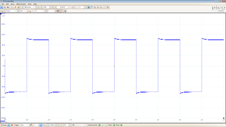
 Assuming the rectangle signal from the SG is free from issues, the displayed waveform is easy to correct by adjusting a yellow screw in the probe body, using the plastic trimmer tool from the probe kit. From my experience with oscilloscopes this procedure is either forgotten, neglected, or ignored, always resulting in frustration with users chasing “strange” signals using their “gigasamples” scopes when in fact all is well and their probe is a fraction of a pF off the ideal match to the scope input.
When connected to the PC’s USB port the 2208B MSO powers up and makes itself known with a light, rapid series of clicks from what I guess are reed relays in the box, passing a reset & verification procedure. The same little music is heard when you press the Auto Setup button in the control display to enable the scope to figure out a set of initial, global, get-u-going, setting to best display your waveform. I admit to having used that Auto Setup button a lot when I was confused with my beginner’s settings to grapple with complex signals, especially the trigger and delay stuff. It’s a much advanced version of pressing Beam Find on a ‘scope some 60 years older than the Pico.
Coming from the CRT era I was delighted to read in the Getting Started manual that your first test on the up and running Picoscope should be to touch the probe tip and view the 50 Hz (or 60 Hz) waveform known as “hum”! Hey presto:
Notice the uncluttered screen with maximum size given to the measured signal. There’s lessons to be learned there, Microsoft people!
The probes
Again coming from the CRT era I was delighted to see Pico give a fair share of attention to the matter of The Probes. These are so underrated in this day and age with all that plug & play and digital error correction around they warrant a short discussion. My 2208B DSO came with two TA132 probes. Depending on the USB scope type, Pico supply a pair of TA131, TA132, TA159 or TA160 probes. Here, I was confused. Reading the specs table found in the probe package, initially I was unable to find any difference between the four TA’s except the rise time in the x10 position. Unless there are typos in the table, the TA160 is exactly the same as the TA131, and the TA132, the same as the TA159. Electrically, that is.As an exercise in working with the USB scope or indeed any oscilloscope I would recommend doing the Frequency Compensation Adjustment.
I used the 2208B MSO's internal Signal Generator set to 1 kHz squarewave, 1 Vpp, to drive Channel A. The BNC-to-probe tip adapter included in the probe kit allows you to connect directly to the AWG output on the 2208B MSO. Okay, waveform appears but is not stable. Click on Auto Setup. Then select: Auto from the Trigger menu and the signal is steady. I found both probes exhibiting “overshoot” of the rising edges and wanting capacitive compensation:
Assuming the rectangle signal from the SG is free from issues, the displayed waveform is easy to correct by adjusting a yellow screw in the probe body, using the plastic trimmer tool from the probe kit. From my experience with oscilloscopes this procedure is either forgotten, neglected, or ignored, always resulting in frustration with users chasing “strange” signals using their “gigasamples” scopes when in fact all is well and their probe is a fraction of a pF off the ideal match to the scope input.Read full article
Hide full article

About Jan Buiting
Jan Buiting (1958) has been active in electronics and ways of expressing it since the age of 15. Attempts at educating Jan formally have so far yielded an F-class radio amateur license, an MA degree in English, a Tek Guru award, and various certificates in ele... >>
Discussion (0 comments)