
AI-Based Water Meter Reading (Part 1): Get Your Old Meter Into the IoT!
on
Smart water meters have already been on the market for some time, but replacing our old meters is often not so easy, for technical or bureaucratic reasons. With this project, an analog meter of any kind can be turned into a digital one using an ESP32-CAM platform and an artificial intelligence (AI) system. Because we will also unveil a lot of background in this article, we have split it in two parts.
Italy is one of the European countries that withdraws and consumes the most water for civilian use, second only to Greece. These numbers are worrying, especially considering the water crises that punctually hit our Country. Average availability, in fact, has declined by about 19% in the last three years, worsened by increasingly hot temperatures and a shortage of rainfall. This problem is not unique to Italy, and several nations are taking drastic countermeasures, such as limiting consumption or allocating funds to renovate private or state-owned distribution facilities in order to avoid leaks.
In addition, given the continuous evolution of technology, several distributors have been taking steps for a few years now to make the reading of civilian meters more efficient as well. This measure serves to avoid wastage of the raw material, but also to reduce the reading operations performed house by house by operators.
In this article, we are going to address this issue: reading an analog meter to make it digital and have it transmit the values to us or to one of our servers. The whole thing is based on an ESP32-CAM, a platform already known to many, and an AI system that can go and detect and translate photos into potential readings.
Architecture
AI systems have entered our daily lives in a big way, just think of voice assistants or image recognition. For the complex computations that an AI system has to deal with, it is possible to rely on cloud computing on dedicated online platforms, or to perform them directly on the chip, in so-called edge computing. With the increasing enhancement of processors, this second mode of processing is expanding and is the basis of our project.
In this, an AI network and an ESP32-CAM will cooperate in order to be able to give the user a digital result obtained by digitally photographing a classic analog water meter. The recognition and digitization is done by the ESP32-CAM using a convolution neural network (CNN), which we will deal with later in the article.
The first step in implementing our project is to install the firmware on our ESP32-CAM. Next we will need a calibration phase in which we will identify the areas designated for recognition of the numbers and indicators on our counter. Once this is completed, we will have all the information available to send it digitally where we wish.
Neural Networks and AI
Neural networks are computational models inspired by the workings of the human brain. They are AI systems that attempt to emulate the way the brain processes information. Neural networks are used in machine learning, which is a field of study concerned with training computers to perform certain tasks without being explicitly programmed for that purpose.
Neural networks play a critical role in deep learning models, which is a branch of machine learning that focuses on processing complex data. They are composed of computational units called artificial neurons or nodes. These neurons are connected to each other through artificial connections called weights. Each connection has an associated numerical value, which represents the importance of the connection to the model.
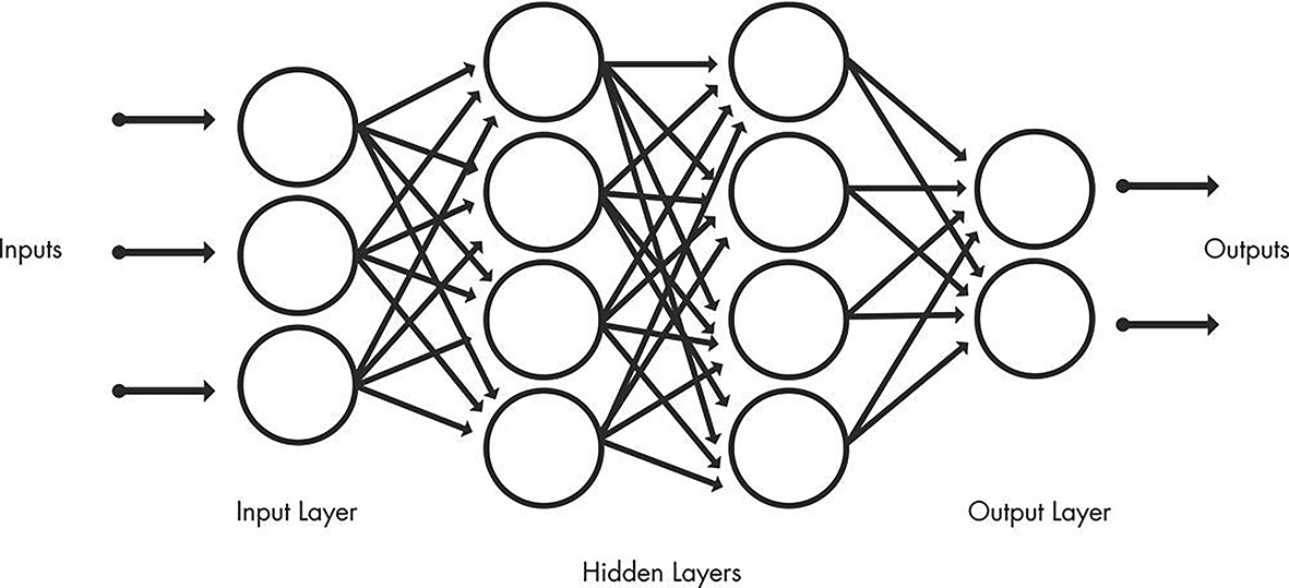
Neural networks are organized in layers, with one or more layers hidden between the input layer and the output layer. The first layer, called input layer, receives the input data. The middle layers, called hidden layers, process the information through their neurons. Finally, the last layer, called output layer, produces the desired results, as schematized in Figure 1.
Neural networks can be used in a wide range of applications, such as machine translation, natural language processing, medical diagnosis and, in our case, image recognition. In this specific case, during the training process, filters are applied to the image at different resolutions, and the output of each processed image is used as input for the next layer. The filters start with basic features, such as brightness or edges, and become increasingly complex as they progress, including features that uniquely define the object.
Convolutional Neural Networks (CNNs) are a specific type of neural network designed for efficient processing of structured data, such as images or video. What distinguishes CNNs from traditional neural networks is the use of an operation called convolution. During convolution, a small window called a filter or kernel slides over the input image and a series of mathematical operations are applied to each portion of the image. This process allows CNN to automatically extract relevant features, such as edges, textures or patterns, from the images efficiently.
These networks also consist of an input layer, an output layer and many intermediate layers called hidden layers. They contain three main types of layers, namely:
- Convolutional layer
- Pooling layer
- Fully-Connected (FC) layer.
The convolutional layer is the first layer of a convolutional neural network. It is responsible for extracting the salient features from the input image. Convolutional layers may be followed by other convolutional layers or pooling layers. Subsequent convolutional layers continue to process features extracted from previous layers, allowing the network to learn increasingly complex and abstract features.
The fully connected layer, also called output layer, is the last layer of a CNN. At this level, extracted features are used to make predictions or classifications. This level is responsible for providing the final output of the convolutional neural network.
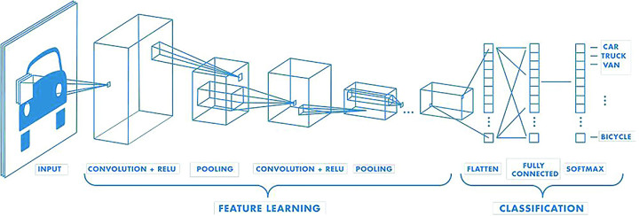
At each level, the complexity of the CNN increases as the network learns increasingly sophisticated and abstract features of the input image. Moreover, as one proceeds through the convolutional levels, the portion of the image that is identified and analyzed in detail by the neural network increases, as illustrated in Figure 2. Unlike a traditional neural network, a CNN has shared weights and biases that are the same for all neurons hidden in a given layer. After learning the features in multiple layers, the architecture of a CNN moves on to classification.
The penultimate layer is a fully connected layer that generates a vector of size K (where K is the number of predictable classes) and contains the probabilities for each class of any classified image. The last layer of the CNN architecture uses a classification layer to provide the output of the final classification. Usually, you have pre-trained models of these networks that obviously weigh several MB or GB. In our case, this will be a couple of MB but will be saved on SD card so as not to burden the internal memory of the chip.
Specifically, there are several files present in the config folder, with the extension tflite, which means Tensorflow Lite. TensorFlow, born out of Google Brain in 2015, has become a reference library for creating Deep Learning models. Initially developed internally by Google, it was made open source and quickly gained popularity among the machine learning community. It offers a wide range of machine learning and deep learning models and algorithms, known as neural networks, and makes them available to developers through an intuitive API.
TensorFlow leverages the power of Python or JavaScript to provide an easy-to-use programming interface for creating applications. Meanwhile, the execution of such applications takes place in C++, which allows for high computational performance. This makes TensorFlow a versatile choice for large-scale machine learning projects.
Models trained with TensorFlow can also be implemented on mobile or edge computing devices, as in our case, as well as on iOS or Android operating systems. The TensorFlow ecosystem offers tools such as TensorFlow Lite, which optimizes TensorFlow models to run efficiently on such devices. With TensorFlow Lite, a trade-off can be made between the size of the model and its accuracy. A smaller model may take up less space, such as 12 MB instead of 25 MB or even more than 100 MB, but it may have a slight reduction in accuracy. However, this loss in accuracy is often negligible, considering the speed and energy efficiency advantages that the compressed model offers.
In our case, this model trained with TensorFlow will be used to distinguish and recognize numbers within the counter and to determine the direction of the indicators. With the help of TensorFlow, we will be able to leverage the power of deep learning for data analysis and AI, improving the efficiency and accuracy of our applications.
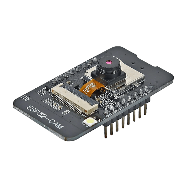
Hardware
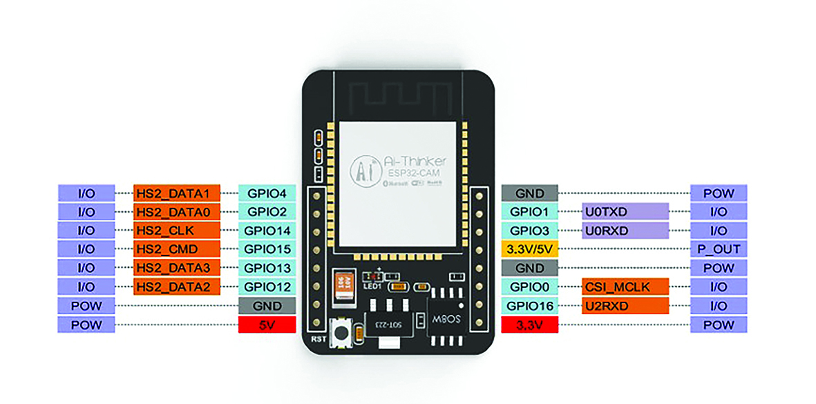
As mentioned, the chosen platform is AI-Thinker’s ESP32-CAM, which thanks to its compact size (40.5 × 27 × 4.5 mm) could be the Holy Grail for any maker. Successor to the well-known ESP8266, which we will discuss later, it consists of an ESP32 module equipped with a connector — whose pinout is visible in Figure 3 — to accommodate a separate camera module and a slot for SDcard up to a maximum of 4 GB. In detail, we can see a programmable microcontroller with built-in Wi-Fi and Bluetooth and an additional external RAM of up to 4 MB.
Not only that, the new camera connector can embed either an OV2640 or OV7670 module; the former comes with the module itself and has a resolution of 2 megapixels. Its SPI speed is 8 MHz and the frame buffer size is 384 KB. Its normal power consumption is 70 mA, while in power-saving mode it drains only 20 mA, making it desirable for its Low-Power feature as well.
There is also a high-brightness LED on board (Figure 4), which can be used as a flash or illuminator of the scene to be filmed. This feature is critical for our project, since it will be placed in environments that are normally very dark. We will see that it will be possible to modulate this light to achieve the desired result. Of course, should the previous one not suffice, the numerous GPIOs mounted on the board allow us to possibly mount an external illuminator in the case of low light.
For small applications, this chip comes across as very robust and with great processing power, relying on 2 x 32 bit cores at 120 MHz. This last feature allows it to have a fairly high frame-rate, obviously depending on the format and size: indicatively we can achieve a throughput of up to 8 JPEGs in SVGA (800x600) per second.
Programming our ESP32-CAM module can be done in several ways: the most classic involves the use of an adapter of FTDI (Figure 5) which, thanks to the FT232RL interface, simulates RS-232 and COM ports, thus allowing a quick Plug and Play of the device.
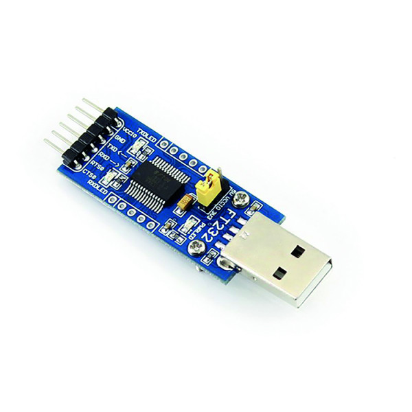
Editor's Note: The module suggested in the “Related Products” frame at the end of this article — fully pin-compatible and available from the Elektor Store — embeds a micro-USB connector with the related serial interface to the chipset, making any external serial adapters unnecessary.
In case you do not have the above-mentioned object available, do not despair; in fact, it can be done from any module in which the TX and RX pins are present, thus from different models of Arduino or ESP.
Wiring for Programming the ESP32-CAM
Just for the reason mentioned above, there can be different types of wiring, similar but different in some respects. In general, the ESP32-CAM module does not have any USB to be able to interface directly with the PC, and that is precisely why we will have to use an external module.
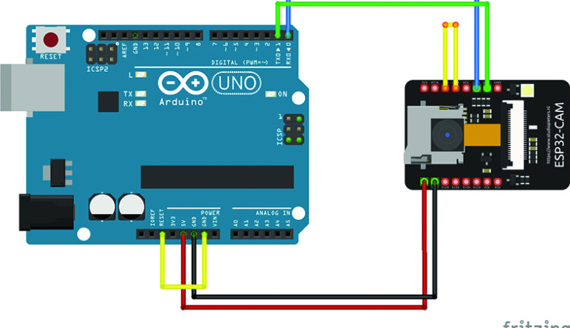
Let us start with the most classic of modules: Arduino UNO. As a first step, we identify the transmit and receive PINs on our ESP32-CAM, called U0TXD and U0RXD, respectively. These will need to be connected directly to the TX and RX PINs on our Arduino. In the camera module, these pins also correspond to the GPIO1 and GPIO3 pins. Next, we short the GND and IO0 contacts on the ESP32-CAM to ensure proper communication. For the power supply, we connect in parallel the 5V and GND pins of the two platforms.
Finally, to reset the Arduino if needed, we short the RESET pin and the GND pin. Summarizing, we get the diagram of Figure 6, also shown in Table 1.

| Arduino ⇒ ESP32-CAM | Arduino | ESP32-CAM |
| TX ⇒ U0TXD | Reset ⇒ GND | GPIO0 ⇒ GND |
| RX ⇒ U0RXD | ||
| 5V ⇒ 5V | ||
If we do not have an Arduino UNO but rather an ESP8266, the wiring changes but very little. In fact, the only change worth mentioning is the contacts to be shorted on our programmer module: they are no longer RESET and GND but EN and GND. The wiring is shown in Figure 7 and indicated in Table 2 as well.
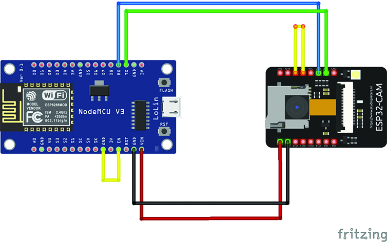
| ESP8266 ⇒ ESP32-CAM | ESP8266 | ESP32-CAM |
| TX ⇒ U0TXD | EN ⇒ GND | RX ⇒ U0RXD |
| 5V ⇒ 5V | ||
| GND ⇒ GND |
Finally, the simplest wiring of all. In fact, if we own a USB/TTL converter module based on the FTDI chip, the whole thing is solved with one less connection. In fact, on the programmer side we will no longer have to short anything, but we will have to exchange the TX and RX contacts with each other as shown in Figure 8 and in Table 3.
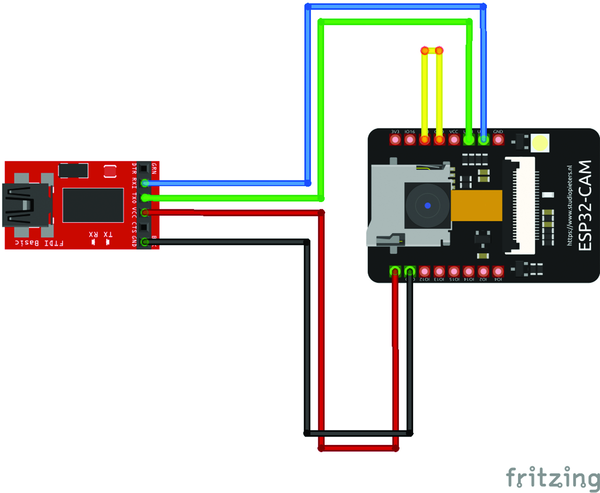
| FTDI | ESP32-CAM |
| RX | U0TXD |
| TX | U0RXD |
| 5V | 5V |
| GND | GND |
The described connections are needed only during the programming phase of the ESP32-CAM. Once the programming is complete, simply power the ESP32-CAM module using only the 5V and GND power wires. It is no longer necessary to connect it directly to the Arduino or make any other wiring.
In the second and final installment of this article, we’ll see the procedure for the firmware installation, the correct set-up of the camera lens for an optimal focusing, the positioning of the reader on the water meter and, of course, the whole AI-based process for the correct recognition and readout of the counter’s elements. Stay tuned!
Editor’s notes: Interested in ESP32 and DIY projects? This project originally appeared in Elettronica IN.

Discussion (1 comment)