
AI at the Edge: Get Started with the Maxim Integrated MAX78000FTHR
on
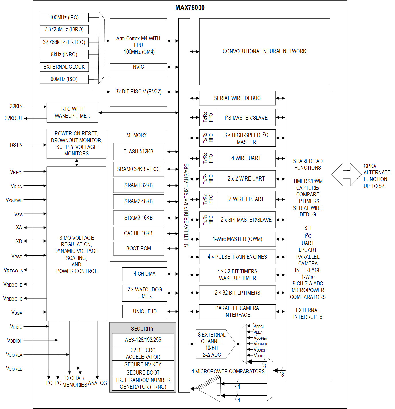
The MAX78000FTHR from Maxim Integrated is a small board based on a MAX78000 microcontroller unit (MCU). This MCU is targeted at artificial intelligence (AI) applications running at the edge. In this context, “edge” does not mean bleeding edge of technology (even though that is what this chip is); it means close to where it is needed or even close to a sensor, instead of somewhere far away in a data centre or so. The edge is, for instance, in your home or in your car or even something you wear. An AI application running at the edge does its work right there all by itself without subcontracting the tough calculations to a cloud service. To do so, it requires large amounts of processing power, which is why the MAX78000 combines an ARM Cortex-M4 processor with floating-point unit (FPU), a convolutional neural network (CNN) accelerator, and a RISC-V core into a single device.
Additionally, devices living at the edge are not supposed to consume a lot of energy and so the MAX78000 was also designed for ultra-low-power operation. Being energy-efficient yet powerful, the MAX78000 can, according to its manufacturer, do AI inferences (i.e., answering questions like “who is in this picture?” or “what sound was that?”) in less than 1/100th the energy of other embedded solutions.
A Convolutional Neural Network
A CNN is a special kind of neural network that uses convolution at its heart. Convolution is a mathematical operation often encountered in image and signal processing and you can think of it as a kind of (matched) filtering. A CNN is a set of filters that scrutinize the input signal for certain features. CNNs are particularly useful in sound- and image-processing applications, and it is therefore not surprising that the MAX78000 also integrates a camera interface and I2S for streaming audio. Its CNN is optimized for 1D (sound) and 2D (image and video) processing.
Besides the already mentioned modules and peripherals, the MAX78000 includes most common peripherals typically found in a microcontroller and some special functions related to IoT security like a random number generator (RNG) and an AES encryption engine (Figure 1).
What’s On Board?
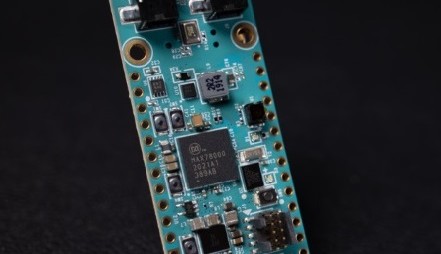
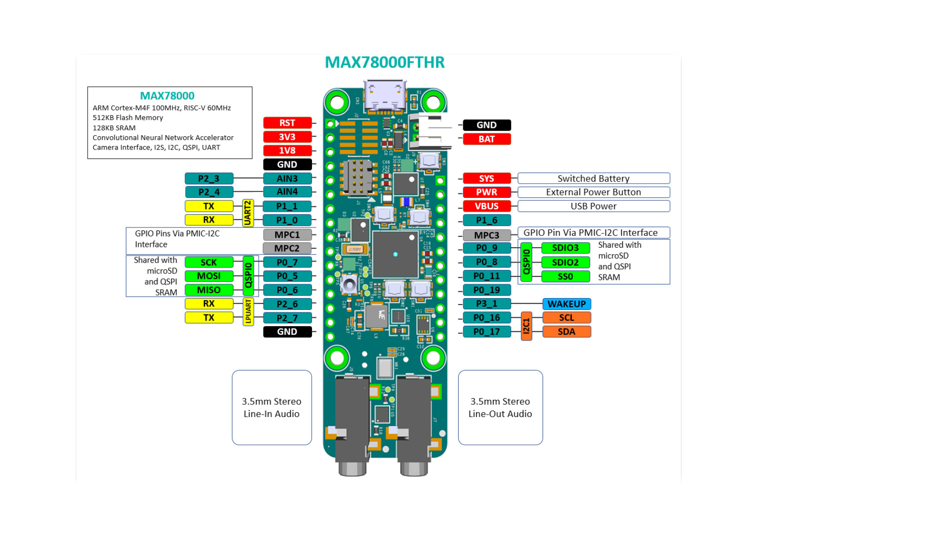
The MAX78000FTHR (Figure 2) is a small module — 66 × 23 mm — featuring the MAX78000, a tiny VGA camera, a digital microphone, stereo audio I/O, a microSD card slot, 1 MB QSPI RAM, an SWD debugger/programmer port over USB and a LiPo battery charger. There are also two user RGB LEDs and two user push buttons and extension connectors compatible with Adafruit’s Feather form factor. A separate JTAG connector is available for programming and debugging the RISC-V core.
When connected to a computer, the board is recognized as a composite USB device comprising a DAP link plus CMSIS DAP WebUSB, a mass storage device, and a serial port. The board comes preloaded with an audio keyword spotting (KWS) demo. If you launch a serial terminal and connect it to the board's serial port, you will see instructions for using the demo.
What Can You Do with It?
Out of the box, the demo recognizes the English words “Zero” to “Nine”, “Go”, “Stop”, “Left”, “Right”, “Up”, “Down”, “On” and “Off”. When it detects the word “Go” the demo enters number recognition mode in which it will blink an LED the number of times as commanded by the speaker. In other words, after saying “Six”, the LED will blink six times. “Stop” returns to normal mode. The serial monitor displays information about how confident the demo is about its performance.
To go beyond the pre-loaded demonstration application (for example to implement system control like toggling a GPIO or transmitting data over another interface), a development environment is required. For this, Maxim has prepared the Maxim Micros SDK that you can download for free from their website.
The SDK is an Eclipse-based toolchain that can also be used with other ARM-based MCUs from Maxim. It contains the Eclipse IDE, MinGW, GCC toolchains for ARM and RISC-V processors, OpenOCD, and a few other utilities. Furthermore, the SDK contains libraries, examples, and documentation; in short, it is all you need to get going on Windows.
Get Going
Launch Eclipse MaximSDK and select or define a workspace. Make sure there is no whitespace in the path. If there is, then either Eclipse won’t be able to compile projects or your workspace may not be where it should be.
When the IDE opens, you will see a welcome screen that you can ignore and close. You can now either create a new project or import an existing one.
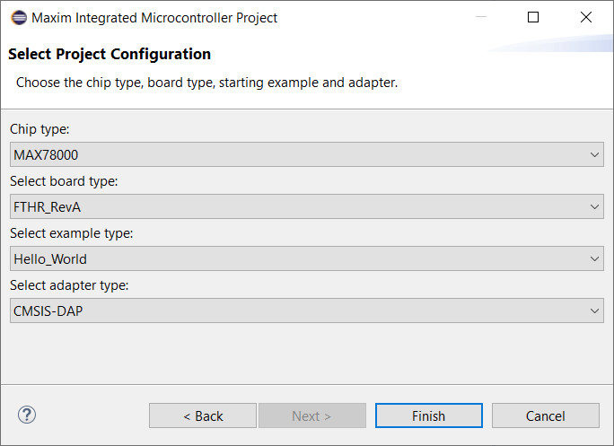
To create a new project, expand the line C/C++ and select the Maxim Microcontrollers wizard, click Next and enter a name for the project. Click Next once more and, in the dialog that opens, set the Chip type to MAX78000, the board type to FTHR_RevA, and the adapter type to CMSIS-DAP. As example type choose something that resembles best what you are planning to do and click Finish to create the project (Figure 3).
Select the Right Board
Now you must first fix the project because even though you selected the MAX78000FTHR board, the project is created for the MAX78000EVKIT. This is something to keep in mind as almost everything in the SDK defaults to this kit. There are two ways to select the correct board (you can even do both, but it won’t work any better):
- In the section Specify the board used of the makefile, uncomment the FTHR_RevA board and comment out the EvKit_V1 (Figure 4). When done save the file.
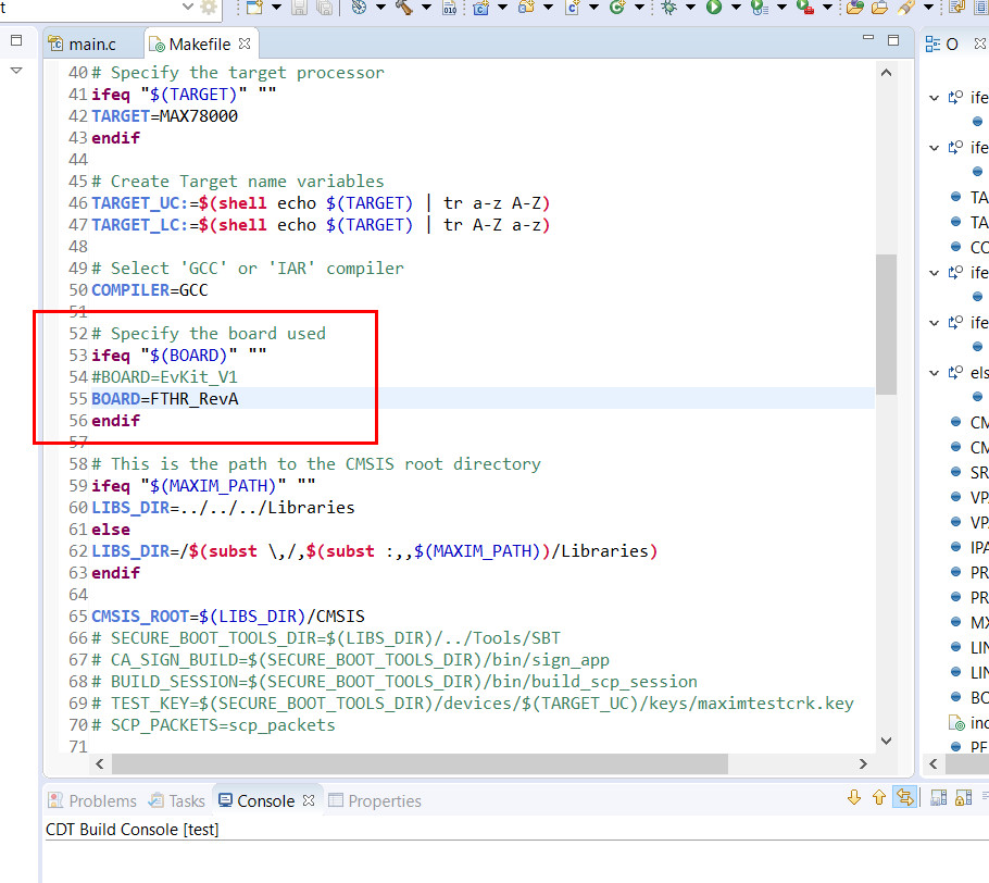
Figure 4: The makefile defaults to the MAX78000EVKIT and must be edited before using it with the MAX78000FTHR. - Edit the build command, accessible through the project’s properties dialog in the section C/C++ Build. Add BOARD=FTHR_RevA to the build command box (Figure 5) and click the button Apply and Close.
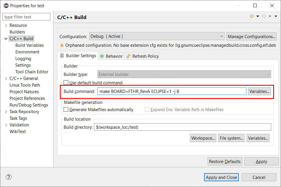
Figure 5: If you prefer leaving the makefile untouched, then add the MAX78000FTHR board definition to the project's build command.
Just to be sure, clean the project before continuing. Clean is available from the Project menu or after a right mouse click on the project in the Project Explorer window.
Now build and run or debug the project. Clicking run (the green dot with a white triangle) or debug (the tiny bug) may bring up a window entitled Create, manage and run configurations. If it does, expand the line GDB OpenOCD Debugging and select your project before continuing.
If you started in debug mode, the program will be halted at the beginning of main. Use the commands available from the Run menu to step through the program and inspect variables.
Import an Example
From the File menu, click Import… to import an example. Expand the first line, General, and choose the wizard Existing Projects into Workspace. Enter the root directory. For the SDK examples, this is MaximSDK\Examples\MAX78000. This will get you a list of examples from which you can select the ones you want to import. You can even import them all if you like.
To continue our keyword spotting journey that we started earlier, Deselect All and then check kws20_demo. Also check Copy projects into workspace as we are going to modify the example and we want to keep the original.
Note that there are a few projects that need files that are not inside their containing folder. These files do not get copied when you copy a project and compilation will fail. You must either copy these files yourself or edit the makefile to repair the path to these files. The cats-dogs_demo project for instance requires the Common folder, so copy that folder too (instead of using the original example or, even worse, making the example folder your workspace).
After importing the example project, change its target board as described above. Build the example and try it out. If all works fine, you can modify it.
I changed the KWS demo so that it makes pin P2.3 high when it hears the word On and clears the pin when it recognizes the word Off. Depending on the keyword, the LED will either be green (On) or red (Off). If another keyword was recognized, the LED turns blue, but the pin doesn’t change state. Pin P2.4 indicates confidence. When the inference confidence is too low (≤95%), this pin goes low.
Finally, I added UART2 to the mix. This serial port is available on the extension headers and so it can be connected to another system to act on the data coming in over this link. All the keywords that are recognized with a probability higher than 95% are sent over this link. The keywords On and Off are preceded by ‘Y,’, the other keywords start with ‘N,’. In case of low confidence the string starts with ‘?,’. Feel free to change this arbitrary encoding scheme into something more useful for your application.
You can download my project from GitHub. There you can also find a pin-toggling version of the cat/dog detector demo that outputs extra data on UART2.
MAX78000FTHR: Things to Consider
As you prepare to start working with the MAX78000FTHR, keep the following things in mind.- The voltage level on the I/O ports defaults to 1.8 V. You can change this per pin by filling in the vssel field of the mxc_gpio_cfg_t structure when the pin is configured with the function MXC_GPIO_Config. For 3.3 V you want MXC_GPIO_VSSEL_VDDIOH (default is MXC_GPIO_VSSEL_VDDIO, without the ‘H’ at the end).
- The voltage level issue is also true for the alternate pin functions like TX and RX of UART2. However, their pin configuration structures are somehow read-only so you cannot change the vssel field. A workaround is to copy the structure first, modify the copy and then use it to (re)configure the pin like any other pin. If you know of a better way for doing this, please let me know.
- The function MXC_GPIO_OutPut did not let me set the value of a pin, I had to use MXC_GPIO_OutSet and MXC_GPIO_OutClr instead. The cause appears to be the pin value passed in. Zero works as expected, but not 1. To make it work, pass it as −1 (minus one, i.e. 0xffffffff)…
- Maxim has created repositories for the MAX78000 boards and tools at GitHub where you can find the latest versions of everything including tutorials and examples.
- The SDK comes with MinGW as an alternative to Eclipse. So, if you prefer a console instead of an IDE, you are all set as well.
- The tiny camera on the MAX78000FTHR may have some protective film on it (Figure 6). Make sure to remove it before trying out camera-based applications.
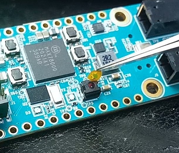
Figure 6: Image processing applications work much better after removing the protective film from the camera module.
Start Experimenting
You are now all set to start experimenting with machine learning and artificial intelligence using the MAX78000FTHR board. In this article, we only scratched the surface of this powerful board and a few more in-depth articles will follow. Here we have shown you how to set up the development environment and how to modify some examples, enabling the use of the pre-trained AI examples in custom applications.
One of the subjects that we have not touched upon is AI training. Although a time- and resource consuming task, it must be done if you want the AI app to work with your data. More information about how to do this can be found in the Maxim repositories at GitHub.
Are you ready to develop innovative artificial intelligence (AI) solutions?
Enter the MAX78000 AI Design Contest (powered by Elektor) for a chance to implement the Maxim Integrated ultra-low-power MAX78000 microcontroller in an exciting new application.

Discussion (3 comments)