
Making Coffee with the MAX78000 and Some AI (Part 2): Development
on
In the first part of this series about the Maxim MAX78000, we presented how to train a convolutional neural network (CNN) to recognize spoken keywords on a Linux PC. The result were several files, holding the CNN and its functions. In this article, we are going to start the development on the Maxim Micro SDK and implement the code to control our coffee machine demo. To give you a smoother start with the MAX78000, we will not only show how the code was created and works, but also how to set up the IDE and some tricks and tips for your own projects.
The Maxim Micro SDK is based on the Eclipse IDE, a well-known, widely spread IDE. Many vendors use the IDE, and due to its customization, it can have add-ons or highly customized looks. Maxim uses an unaltered version of Eclipse IDE with only a few additions to get your MCU project set up with a bit more comfort. This allows for easy maintenance and gives the user the possibility to customize the IDE if wanted.
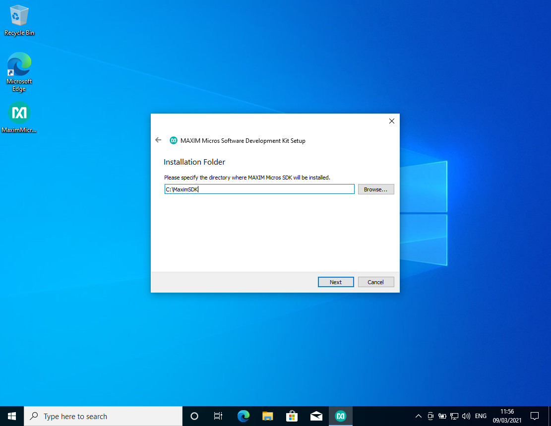
For now, the Maxim Micro SDK only supports Windows, so we will stick to Windows 10 for this project. Also, the default path for the SDK installation (Figure 1) is not touched, as blanks or other special character and Windows paths can cause problems.
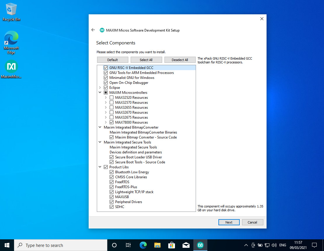
After downloading the installer from the Maxim website, the setup can be executed, and a wizard will show up. If you choose the install options, see Figure 2, only select the MAX78000 as a supported MCU device. This will make the installed size smaller and will put fewer unrequired files on your disk. The installation can take a while and will require an active Internet connection to download additional dependencies.
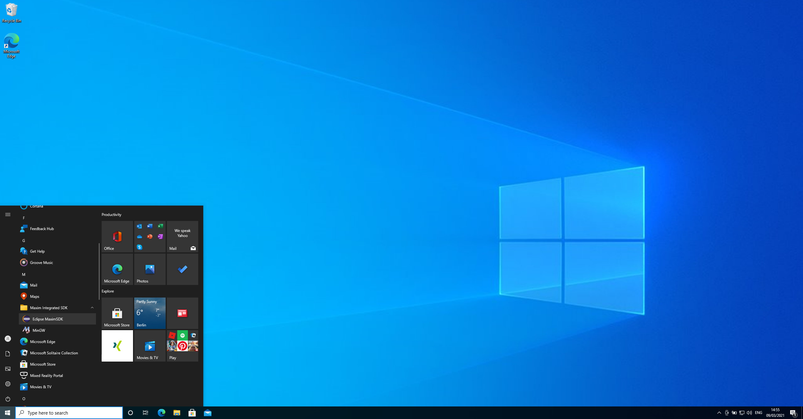
After the installation completes, the Maxim Micro SDK can be started. Just navigate to you start menu and look for Maxim Integrated SDK and choose Eclipse MaximSDK (Figure 3).
The Eclipse IDE, as shown in Figure 4, will appear.
Under Construction
The MAX78000 is a new Maxim microcontroller, and while the hardware is assembled and shipped, the company continues to improve and update the documentation. Visit the MAX78000 GitHub page for the latest documents and software, and also to report any issues you encounter. This is not only true for the documentation but also code involved in the SDK itself. This also applies to the MAX78000 user manual; not all chapters are finalized. For instance, the RISC-V section is still in progress. And you can expect that there will be more parts added in the future to describe this part of the chip a bit more in detail. Consider the Documents and SDK more as rolling release towards version 1.0 as they will improve over time. If you are still missing information, consider asking Maxim for help or dive a bit deeper into the code.
A New Project, Makefiles and Some tricks
We will start a new HelloWorld project to show the basics as well as some hidden items in the Maxim SDK. It isn't a secret that Makefiles are not everyone’s favorite. Depending on what you have used before, most tools will automate the code generation for you. This also includes automatic dependency checks and Makefile generation. Or these tools use other systems like CMake or SCons to generate executables. As we will have Makefile-based projects, some hints will be given to make project starts with added comfort.
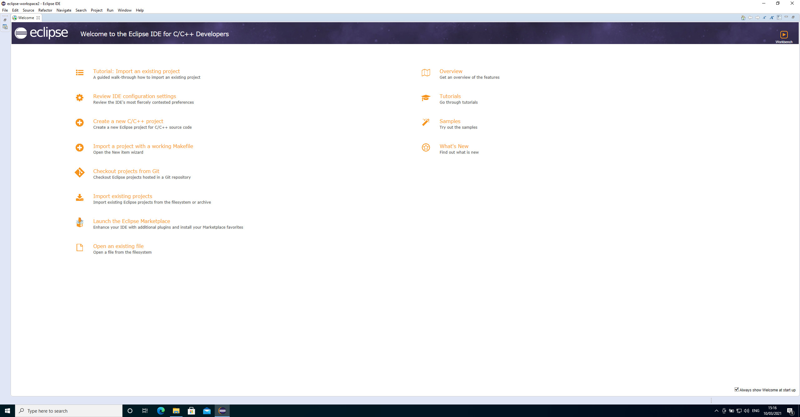
To start a new project, open the Ecplise MaximSDK, if you haven't already. You will be presented with the welcome page (Figure 5).
To start a new project, we use the provided wizard, as seen in Figure 6.
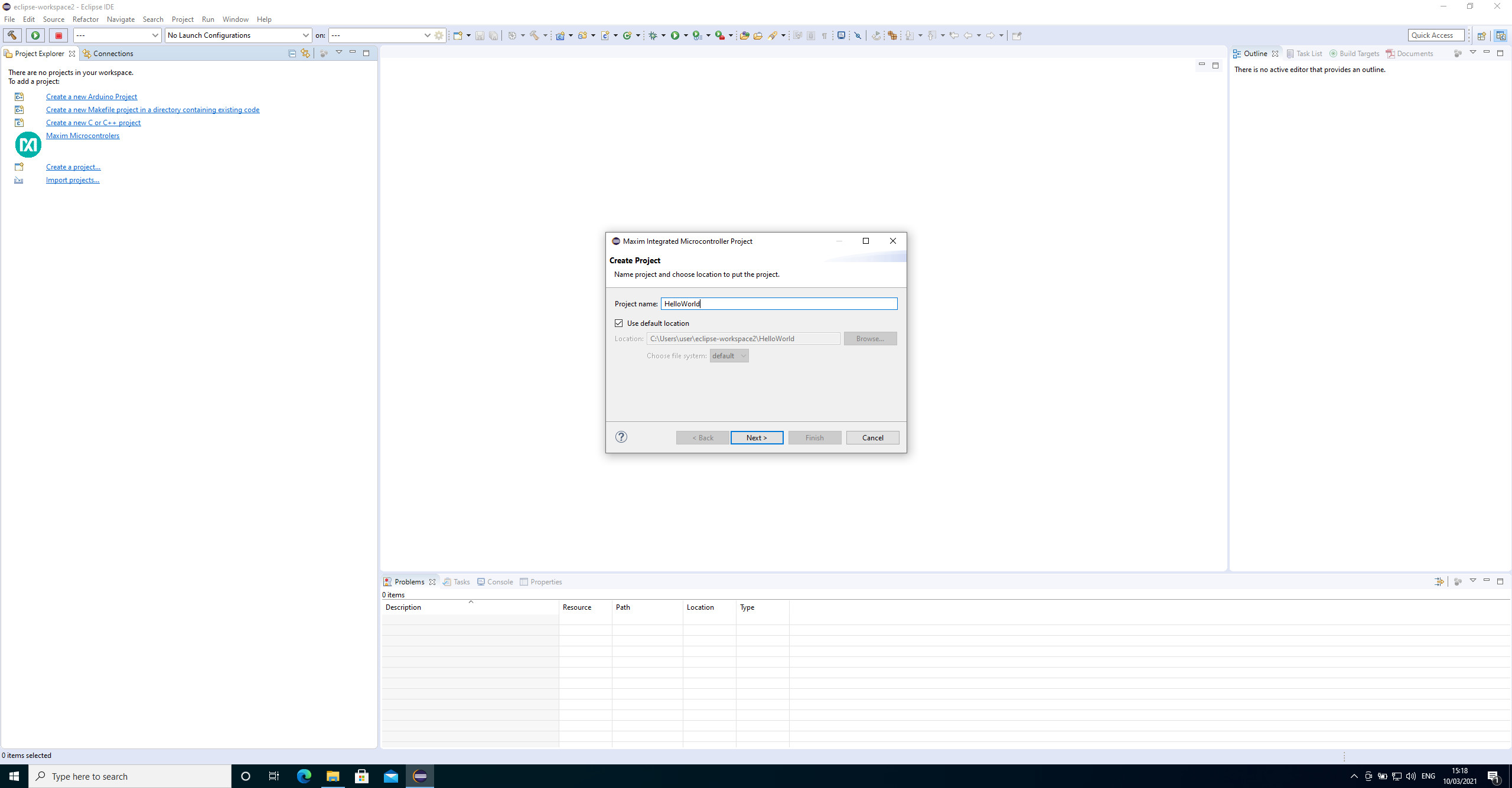
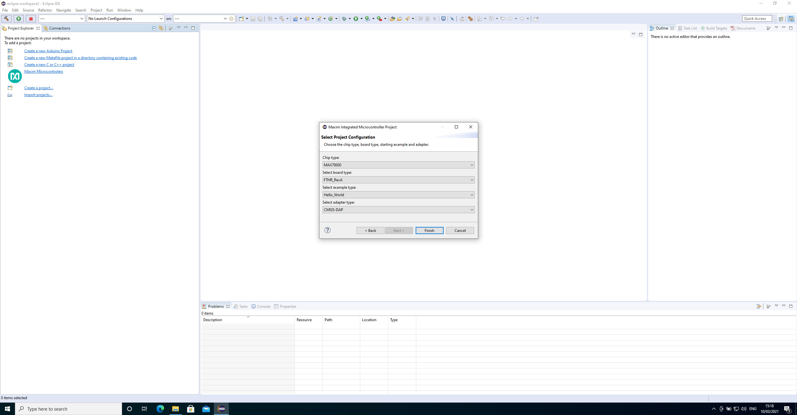
For the project, choose a name and in the following dialog use the same settings as seen in Figure 7.
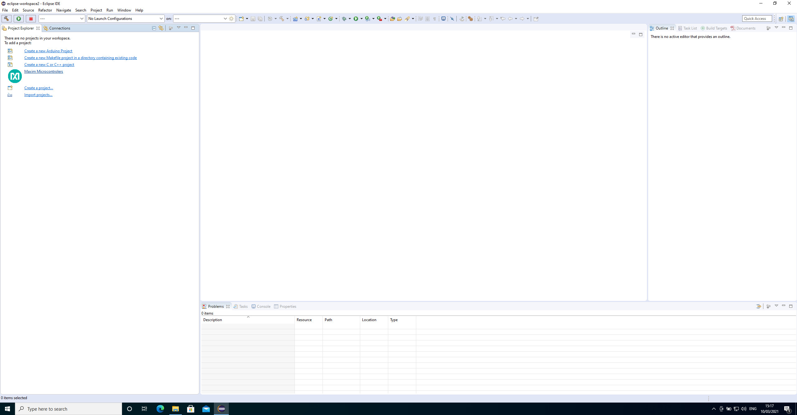
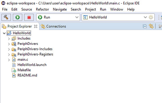
This will copy over the HelloWorld sample project into our own workspace. If you are moving along the list and missing the projects and samples for the AI accelerator, we will address this later. At this point, we are just getting to know the chip and its development environment a bit better. If everything goes according to plan, you will see a new project (Figure 8).
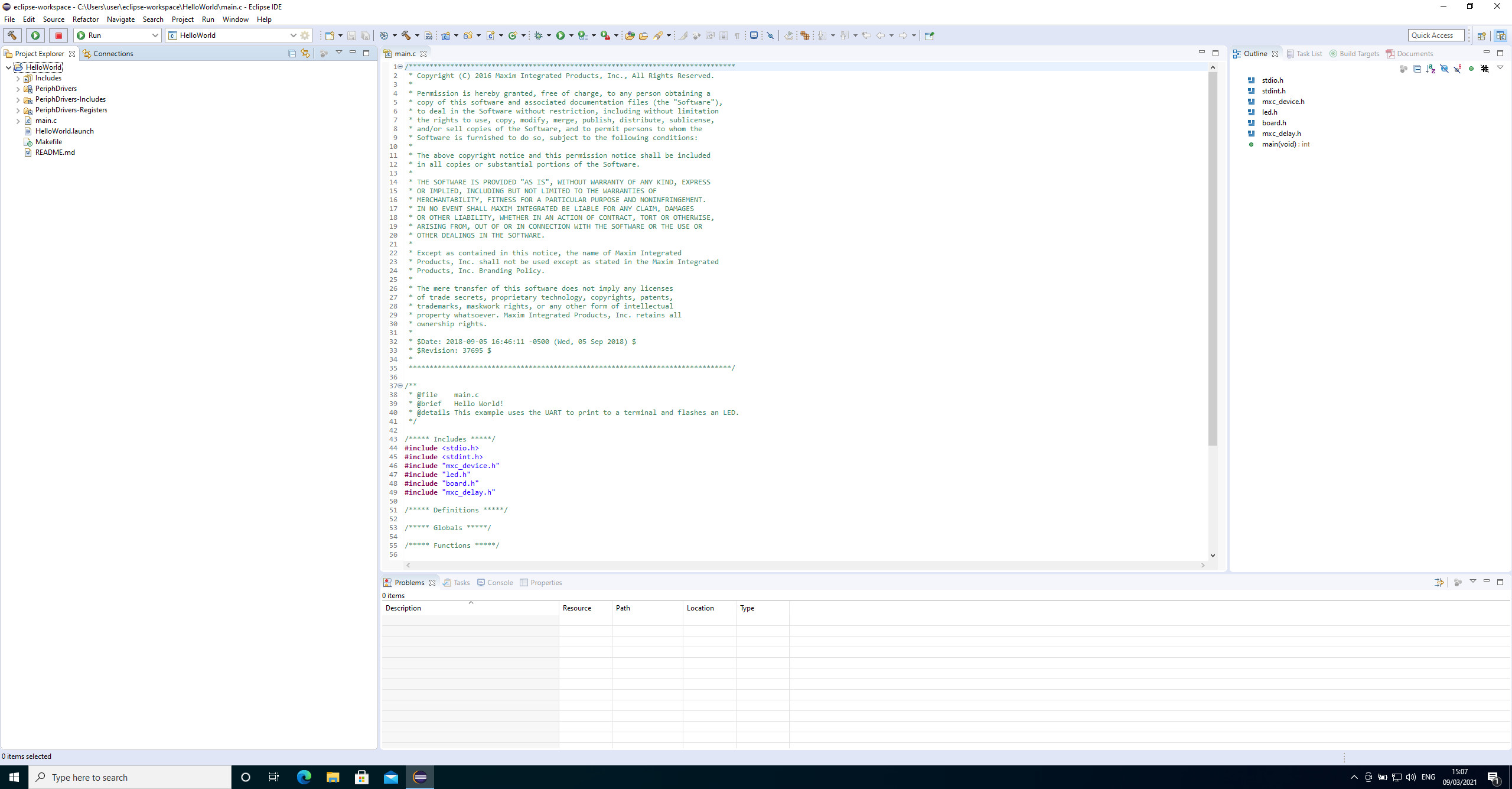
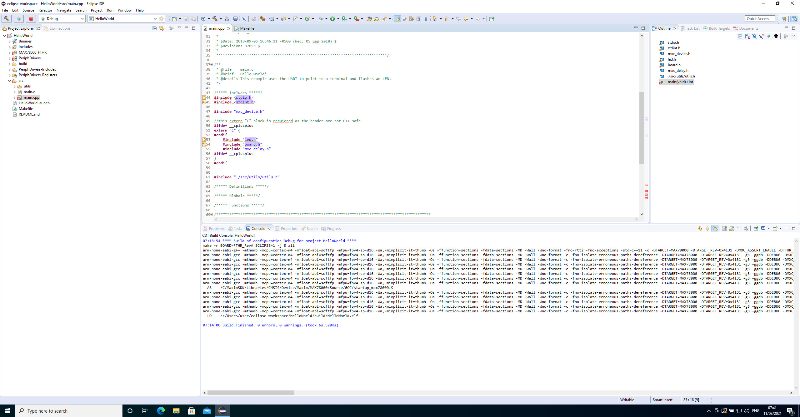
This is a basic HelloWorld project that I will use for explanatory purposes. First, if you look around the code, you will see that many includes and functions cannot be resolved. This is currently a limitation within the setup of the SDK in conjunction with the Eclipse IDE. One advise from Maxim is to have a look at "troubleshooting unresolved symbols" to resolve it. But this is only an issue if you like to navigate with the help of Eclipse through the code. If you are going to compile the code, it will result in an executable that can be flashed onto the MAX78000. To do so, use the small hammer icon (Figure 9) to start compilation.
In the lower windows, you will see some lines of output on a console that should run without any errors. Your first HelloWorld executable is ready and all the recipes to build it are controlled by Makefiles. Therefore, we will have a look at the projects one next.
C and the Makefile
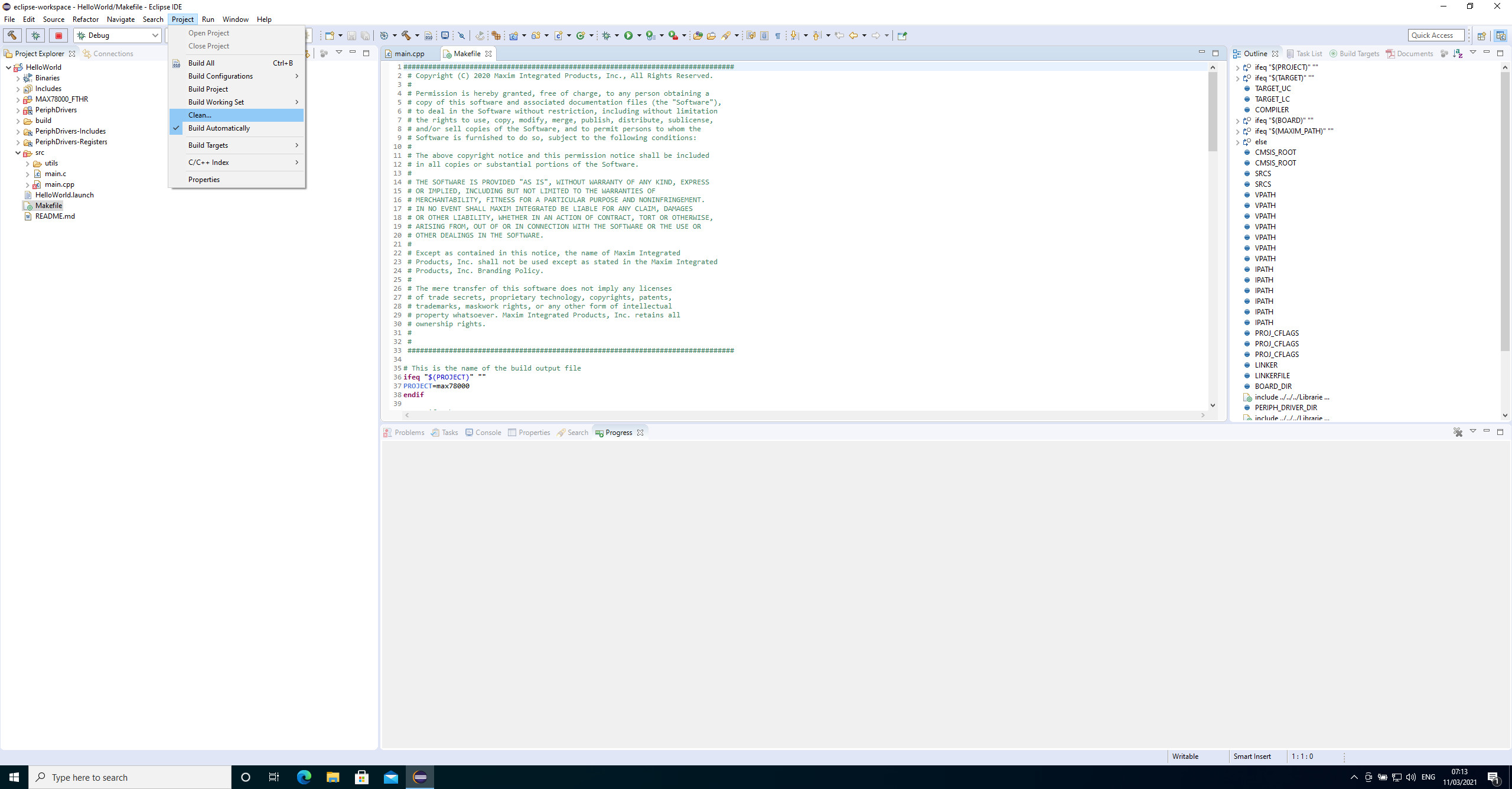
The Makefile — named makefile — is located in your project's root folder. Currently, you see a main.c file that will be used to build C code for the Cortex-M4 MCU core. If we are going with plain C code, this is fine, but what if you intend to use C++? You only need to rename the main.c to main.cpp to let the code be handled as C++ code. If you now hit the compile button, you will see that the Hello World executable is not built from scratch or built at all. Also within the Makefile it is defined what type of evaluation board you use. As default it is assumed you are using the MAX78000EVKIT. As we are going to use a MAX78000FTHR_RevA we need to make, within the Makefile, line 54 BOARD=EvKit_V1 a comment and in line 55 BOARD=FTHR_RevA the # needs to be removed.As Eclipse and the tooling used inside the Makefiles still recognized compiled code in the build folder, a new compilation will not be started, as it seems not required. At this point, we can clean everything manually with some simple mouse clicks as seen in Figure 10.
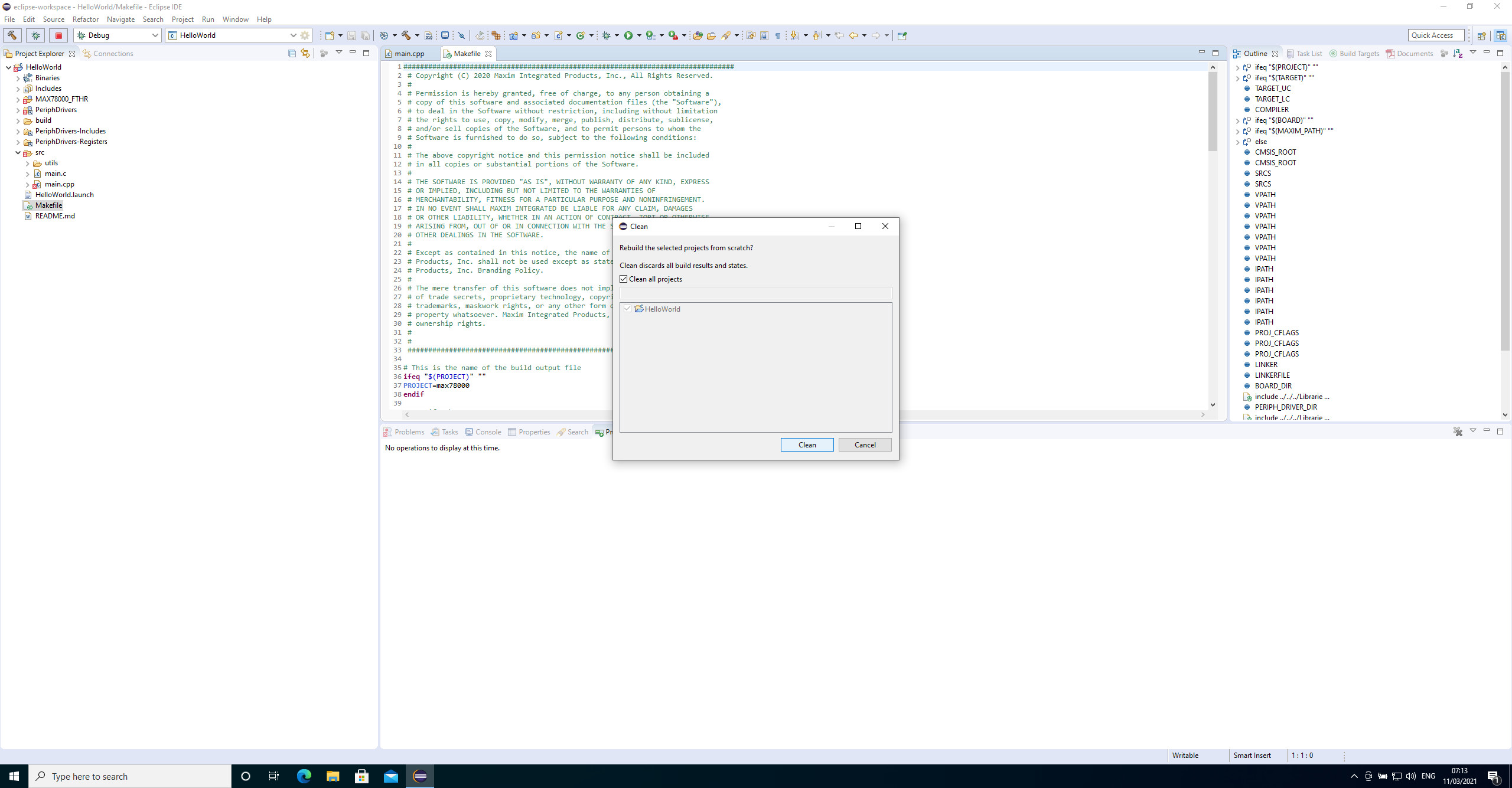
Choose Clean and a wizard windows will appear. As we only have one project, choose all, as seen in Figure 11. This will clean the project and you can have a defined build later.
If we now do compile our renamed main.cpp, the linker will throw errors that some functions and symbols cannot be resolved. The reason for this is the way the C and C++ compiler work and produce their code. As we have renamed our main.c to main.cpp now the g++ compiler gets called. Even as this is a C++ compiler, it understands C code and syntax. Parts of the SDK are still in plain C and will be compiled by the gcc compiler. The linker now needs to mix compiled C++ and C code into an executable.
To get C++ code that can be linked to C code, we need to declare at some points extern "C" to get code that the compiler can form into an executable. This can be done as seen in Figure 12.
It usually should be done within the included header files, if possible. A request for an updated SDK is already done on GitHub and will be processed by Maxim. If you also find parts where improvements can be made, I encourage you to use GitHub and the issue tracker. Whatever you find or request, leave an issue there. Your input will possibly lead to helpful changes or improvements. Also, all the other SDK users will benefit from your feedback.
Change Folders and the Makefile
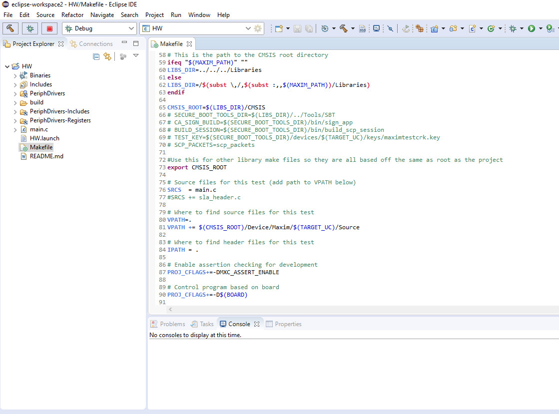
If we now add code to the project, you will soon realize that it is not getting compiled. The reason is within the Makefile. As seen in Figure 13 every file needs to be added to the SCRS line.
As this can get a bit complicated in the beginning, there are ways to automate it. One solution is shown in Figure 14 and will use all code files inside your projects folder.
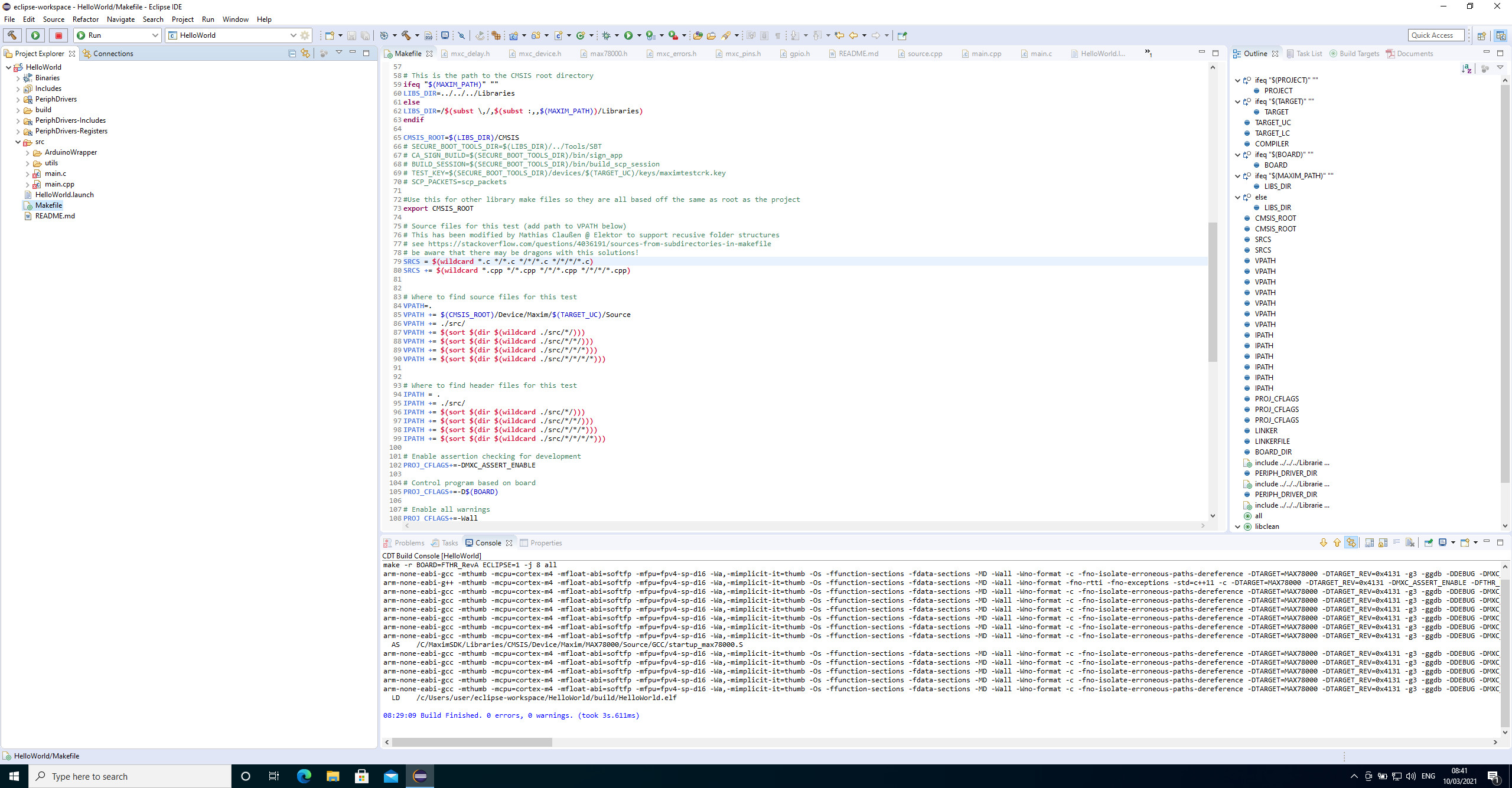
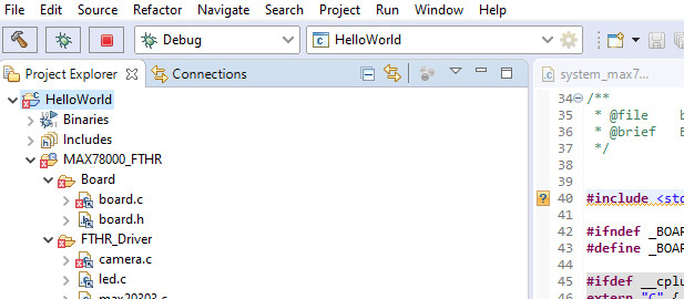
This removes the requierment to include every single source file by hand into your Makefile. Also note that the folder structure is changed. All source files, including the main files, are now located in ./src/ where you can add additional folders and files. Also, you can see that a MAX78000_FTHR folder is added to the project. This are symbolic links to the board support files, start-up files and linker scripts inside the SDK. Also, there you will find some code for onboard peripherals, where available.
Hidden Places
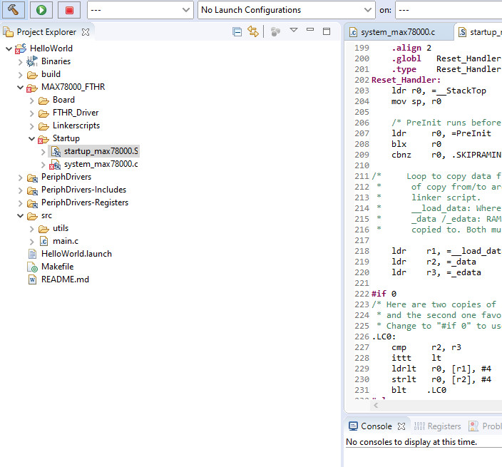
The reason why these symbolic links are added is to give you some details for the board start-up code and where you could change the code for your own needs. As this is a more advanced topic, we cannot cover it in detail here, but we can take a quick tour. As shown in Figure 15 startup_max78000.S and system_max78000.c are responsible for the code that runs directly if the system leaves the reset.
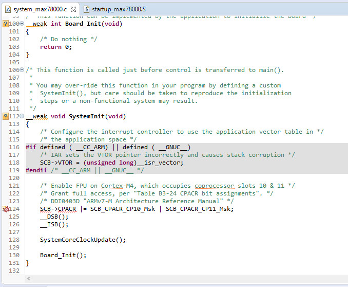
In the startup_max78000.S the Cortex-M4 core gets prepared to execute code and two functions will be called, SystemInit and main. It should now be clear where you can find the main function, but SystemInit will be hidden inside system_max78000.c. As you can see from Figure 16 the function is declared as _weak void SystemInit(void). The _weak key means, if the linker finds a second function that is also called void SystemInit(void) without the _weak key, this one will be chosen and linked.
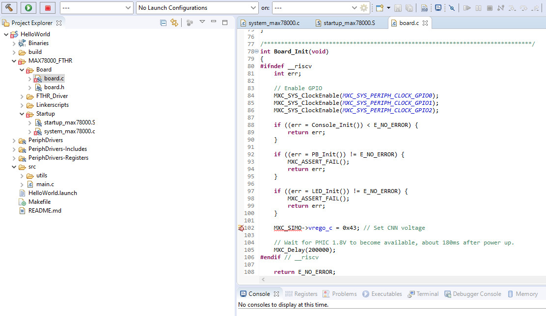
Not only SystemInit but also the two functions it calls, SystemCoreClockUpdate and Board_Init, are declared _weak and Board_Init is also present in the board.c file, as you can see in Figure 17. At this point all basic components will be initialized before the main() is called. These are the GPIOs, UART 0 as serial console, the power regulator, and LEDs. The UART 0, the one connected to the onboard debugger, will be used as default input and output device for all functions that are related to printf. Changing these files are for more advanced use and should only be altered with care if this is your first project.
Choose C or C++ and Send Code to the MAX78000
To begin, first chose C or C++ for your project. If you are going with C++, delete the main.c for our sample project. And if you choose C delete the main.cpp. After our HelloWord is compiled and ready, we need to get it onto the MAX78000. We are going to use the onboard debugger, not only to program it, but also to start a debug session. Select the Debug settings, as seen in Figure 18, clean the project and rebuild it.
If you choose release, it might be that the code will not be present to debug. Hit the icon with the green beetle, as seen in Figure 19, and let the code upload and execute.

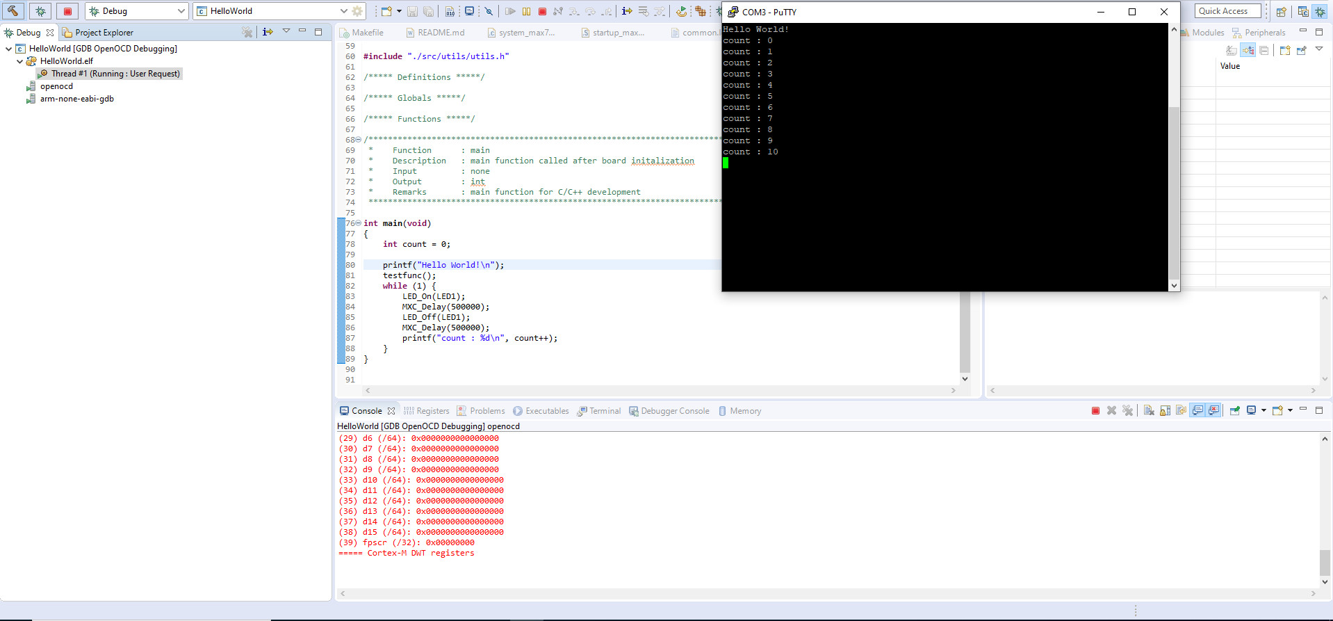
Choose a serial terminal like putty to monitor the data output from the MAX78000. The parameter required are 115200 Baud, 8 data bits, no parity, one stop bit. Connect to the COM port provided by the MAXIM78000FHTR onboard debugger and initialize a serial connection. The result should look like what you see in Figure 20.
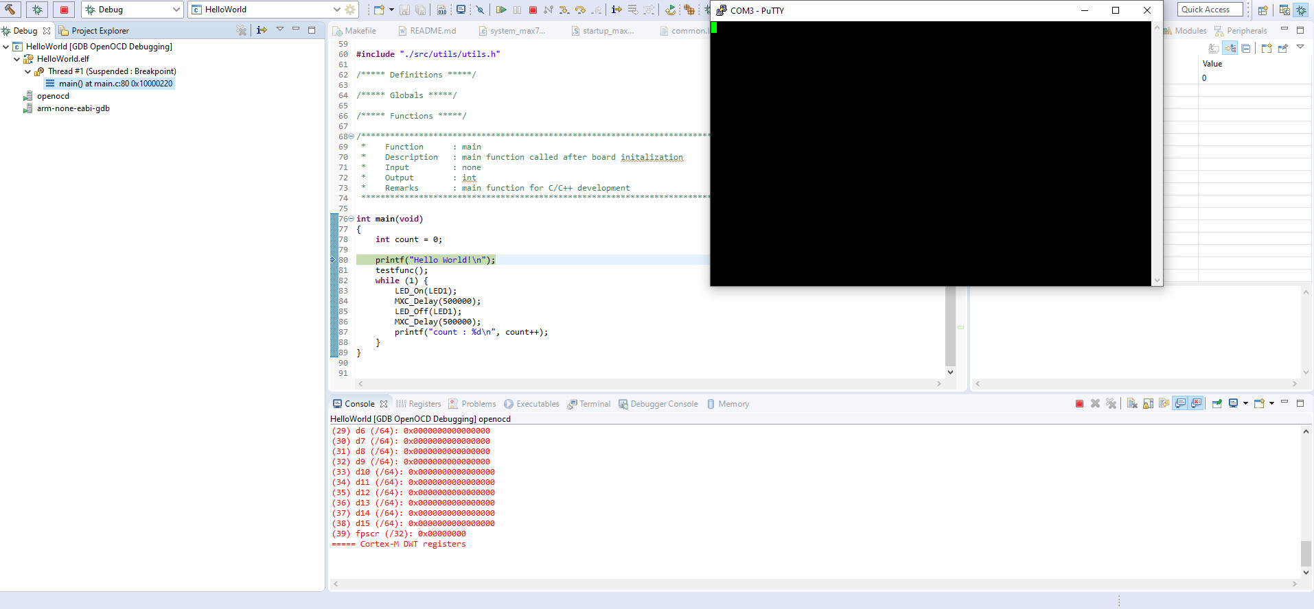
The debugger is attached, the serial monitor is ready to be used and execution of our code has been stopped inside the main function. If we now hit resume (see Figure 21), we will get data shown inside our terminal, as Figure 22 demonstrates.

Explore the Peripherals Step by Step
One bit of advice here: explore the provided peripheral of the MAX78000 step by step. This will give you good insight into the system itself. For all peripherals samples are provided. While you are exploring them, I can recommend having a logic analyzer or digital scope on hand to verify that the system is behaving as intended. A new microcontroller, especially if you are used to other vendors, will take its time to get used to. Also, for all parts, peripherals and tools are provided. This is something not done in a few hours; it will require several weeks or even months. And if you have setbacks or find something behaving strangely, try asking for help or filing issues on GitHub.
AI Examples
Something that you won’t be able to generate based on existing examples with the provided wizard for now are the AI examples for the MAX78000. Those are provided within the SDK, but you need to import them by manually. If you have a look at [7], the guide will show you how to add these examples to your Eclipse working space. Here you will also find the kws20_demo that the coffeemaker is based on.
Building the Coffeemaker
From here on, I will assume that you are a bit familiar with the MAX78000 and have done your first Hello World with it. Below I recapitulate the required parts in case you do not have the first part of this article at hand:
- MAX78000FTHR RevA board (Figure 23)
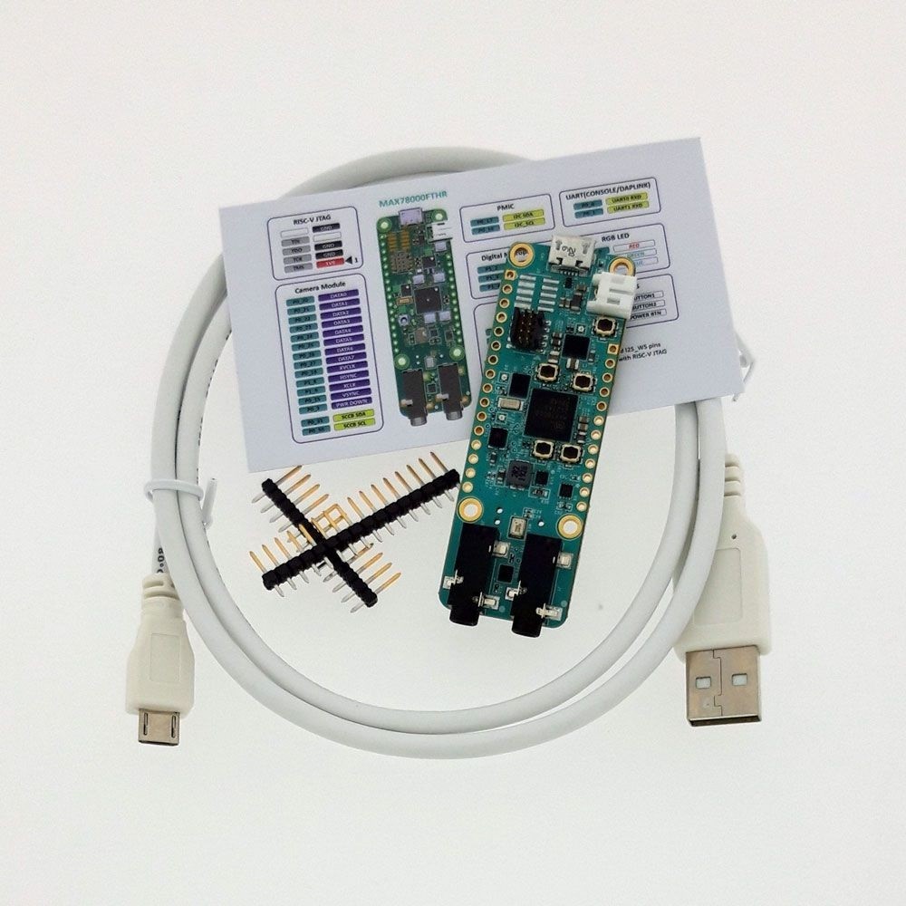
Figure 23: MAX78000FTHR board. - Breadboard
- Jumper wires
- 2.2 TFT Screen from Elektor Store (Figure 24)
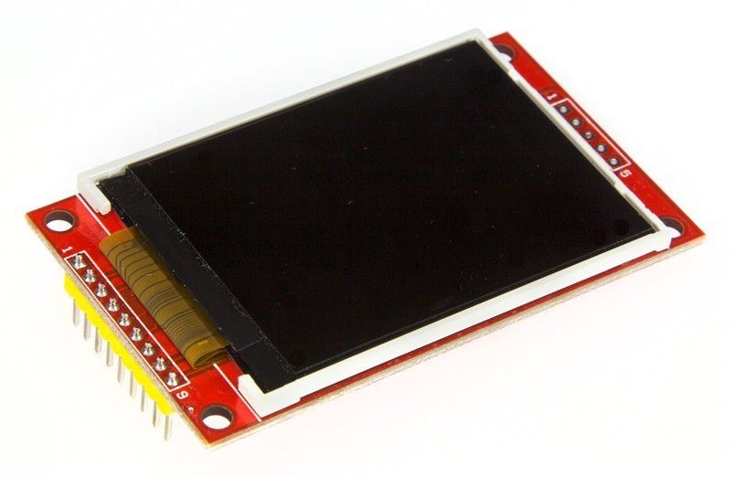
Figure 24: TFT display.
Those components, wired as shown in Figure 25, are the bare minimum for the display.
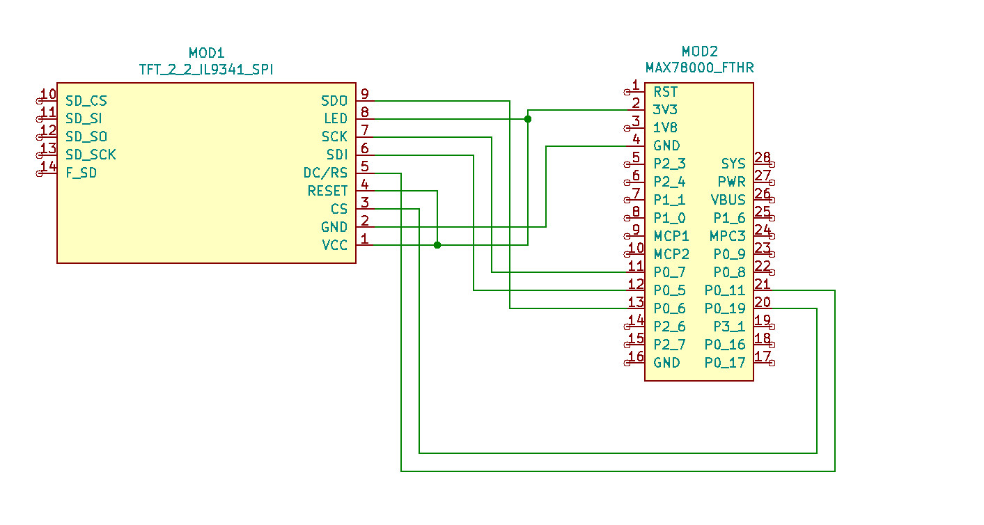
The display was chosen as the SDK already provides a ready made driver for it. This will later allow for some shortcuts, as we don’t have to develop a display driver on our own. The features we are going to implement are:
- Machine shall listen to HAPPY as name.
- Ask if it shall brew a coffee.
- Ask if a cup is inserted.
- User feedback through LCD.
If you are missing an actual coffeemaker in this list, be assured, no working coffeemakers were harmed in making this presentation. As this is a proof of concept, the integration into a real coffeemaker is vendor dependent, and we use a virtual one here. We also need the trained neural network created in the first part. Be sure to have access to the generated files because we will need them later to be partially moved into this project to allow for the recognition of our newly selected words.
Modify the Code
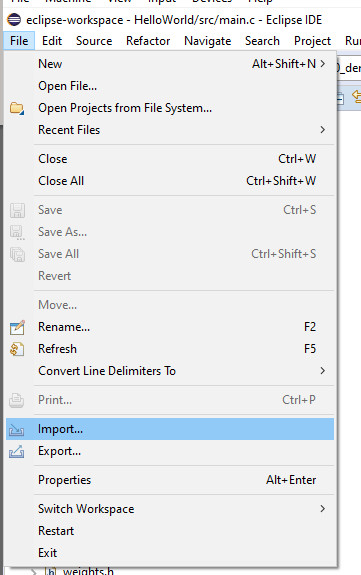
The coffeemaker is based on the kws20_demo project, provided by SDK. The first thing we should do is to verify that our newly trained words are recognized as they should. For this we take a copy of the kws20_demo and place it into our Eclipse workspace. If you have chosen the default path for the Eclipse workspace, the project can be found at C:\Users\{username}\eclipse-workspace. After the project has been copied, we can import it from this location as seen in Figure 26.
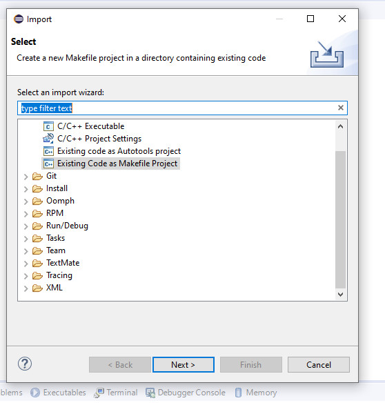
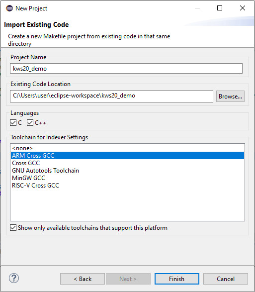
Follow the wizard as shown in Figure 27 and Figure 28.
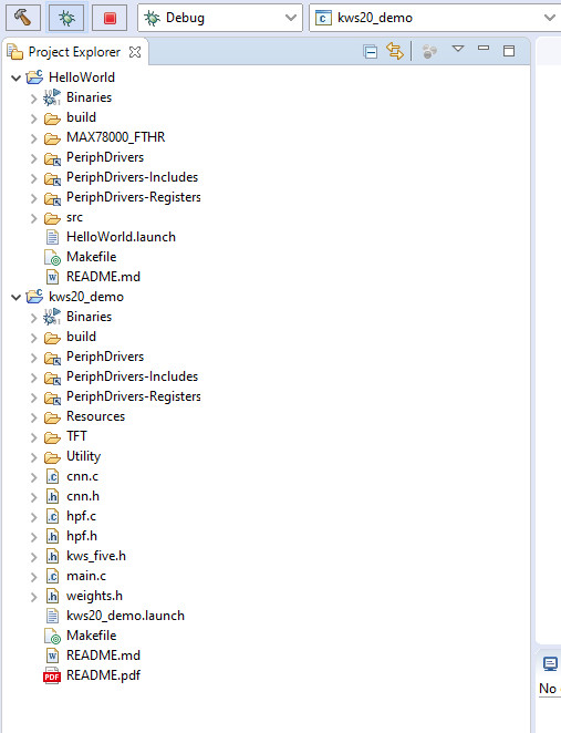
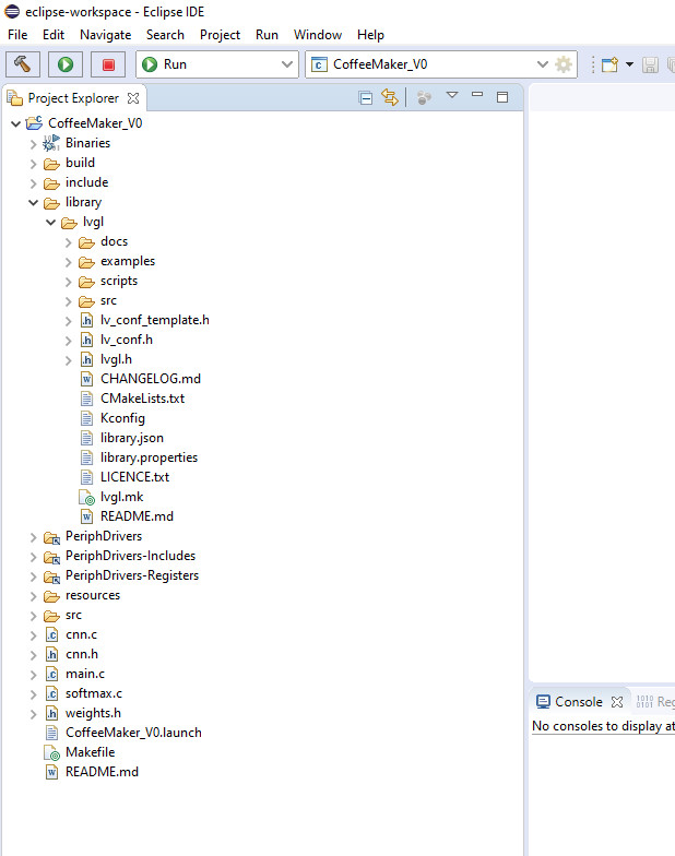
A new project will appear in your workspace as seen in Figure 29.
If you still have the HelloWorld one in your workspace, you can now remove it. First, the code will be built and tested on the MAX7800 board to verify that the provided sample is working. As with the HelloWorld example before, we need to adjust this project for the MAX78000FTHR board. In this case, we need to enter the C/C++ Build settings and enter the Build command. Enter make -r BOARD=FTHR_RevA ECLIPSE=1 -j8 "" and apply the settings as seen in Figure 30.
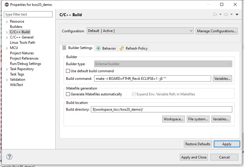
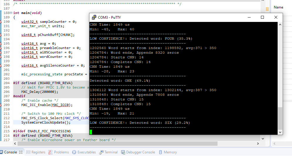
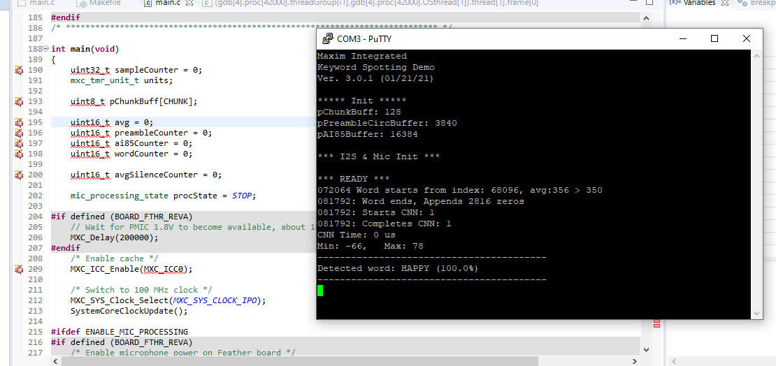
This will allow you to build the kws20_demo for the MAX78000FTHR board. If everything is compiled, we can upload and debug the code. If we attach putty as serial terminal, we can see the output of recognized words as seen in Figure 31.
Put the New Trained Neural Network in Place
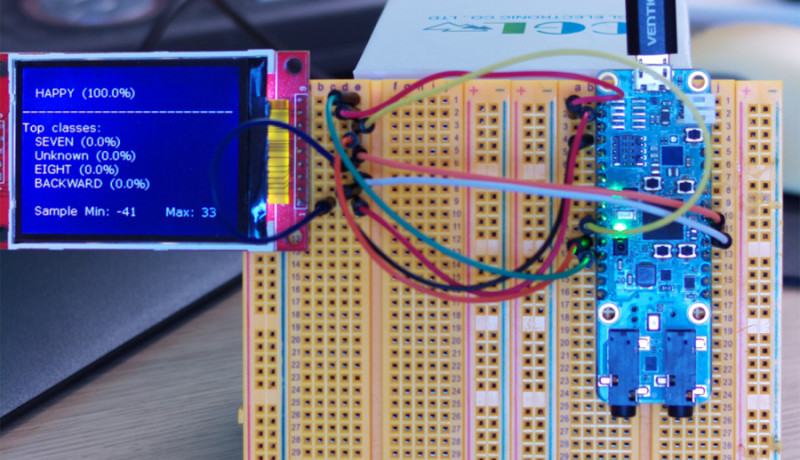
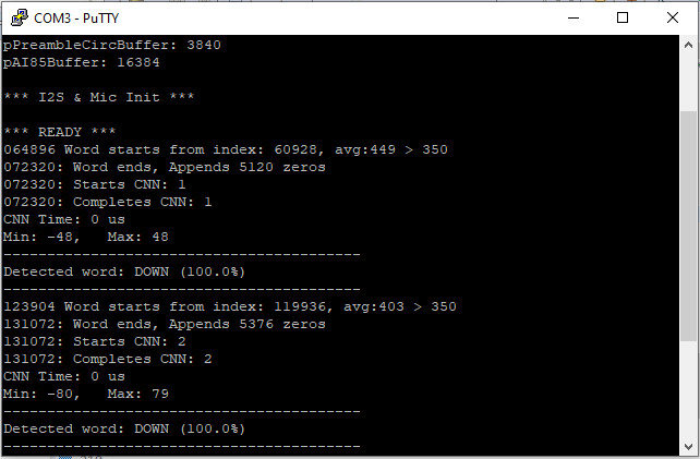
The training we covered in the first part of this series generated a neural network that can be directly moved into this Eclipse project. From our trained project, we need to move the cnn.h, cnn.c and weights.h into the kws20_demo project and replace the current files. After a clean and build, we can test the new neural network on the MAX78000. If the code is uploaded and we use the key word HAPPY, the result will be what you see in Figure 32. If you now wonder why we have DOWN as a recognized key word, we need to have a look into the code.
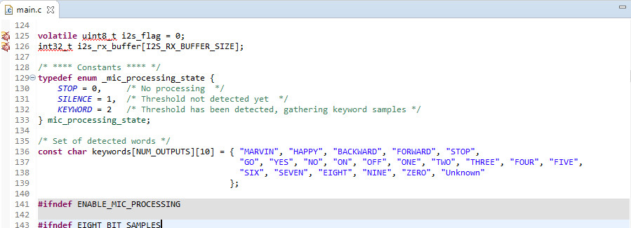
Within our main.c at line 136 (Figure 33) you can see a const char keywords[NUM_OUTPUTS][10] that will hold an array of strings.
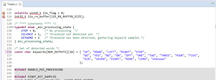
If you now look at Figure 34, you can see that we modified your keywords to be trained for the neural network and the ones for the array in our main.c are not matching.
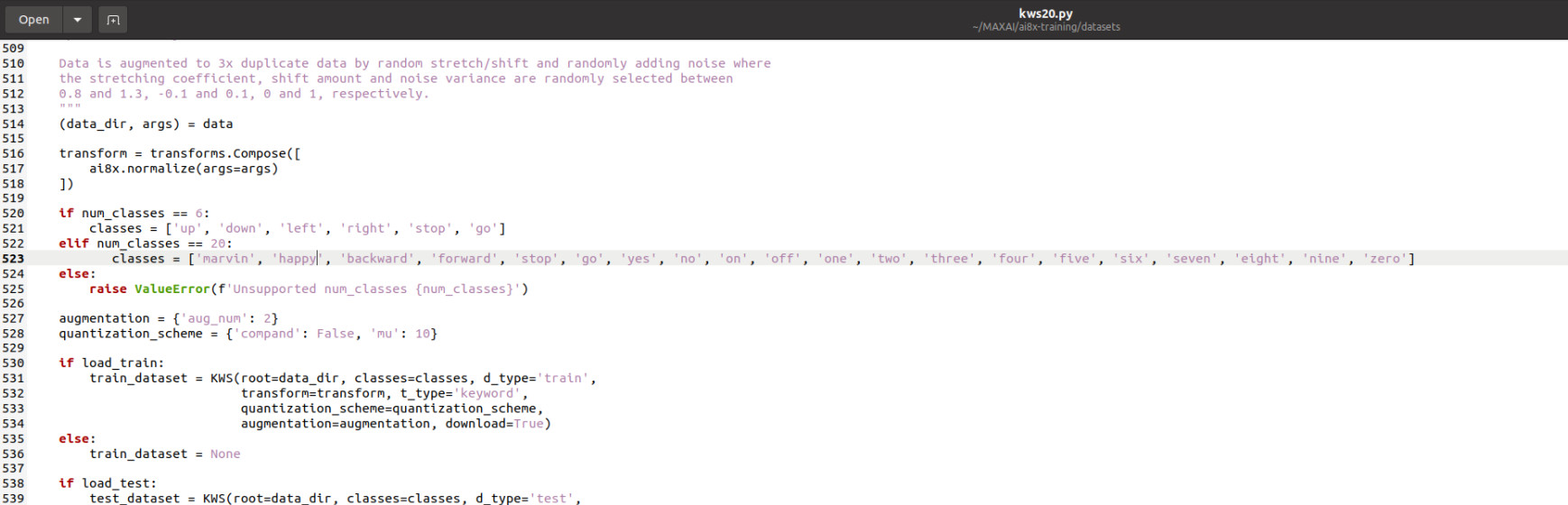
The reason is the way we get the recognized words from the CNN accelerator. For every word we trained, the accelerator will give back an index and a probability of a word we trained. So, to get a correct output, we need to adjust the keyword to match the items in the string array with the index of the words used in our neural network.
If we have the new keywords in place, the code will look like what you see in Figure 35.
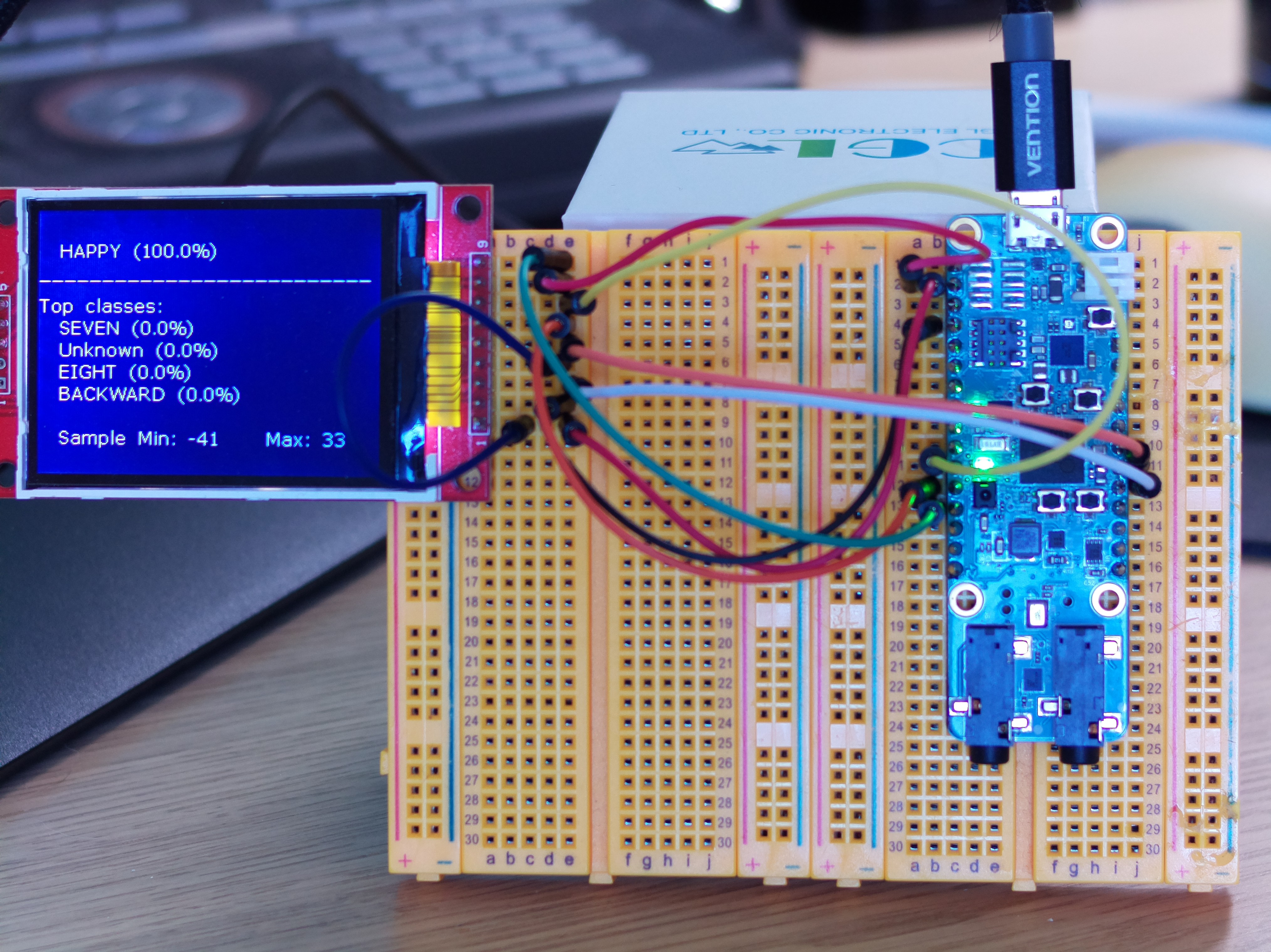
And if we now call HAPPY, we can see an output like what appears in Figure 36.
While we have this part of code working, we have a display attached that currently produces no output. As a quick measurement to get it working, we simply add #define ENABLE_TFT in line 73 of our main.c and do a clean build of the project. A preffered methode would be to use the Maikefile and uncomment the corresponding line. The included driver will work fine with the display, and we can use it later for the coffeemaker. The result can be seen in Figure 37.
Using a GUI Library That Runs on Almost Anything
We now have a working keyword-spotting project that also can output graphics on the attached display. To avoid writing our own GUI library we use an existing one. For this project, we are going to use the LVGL to generate our user interface. Besides being highly portable, the resources used by this library can be minimized. Even with animations and transparency effects we don’t have a lot of RAM to spend. The question is, how hard can it be to add the LVGL library to the kws20_demo project?
As the LVGL uses also Makefiles for its code to build, integration is not that complicated. The code itself is moved into our projects in a library directory. It will look like what you can see in Figure 38.
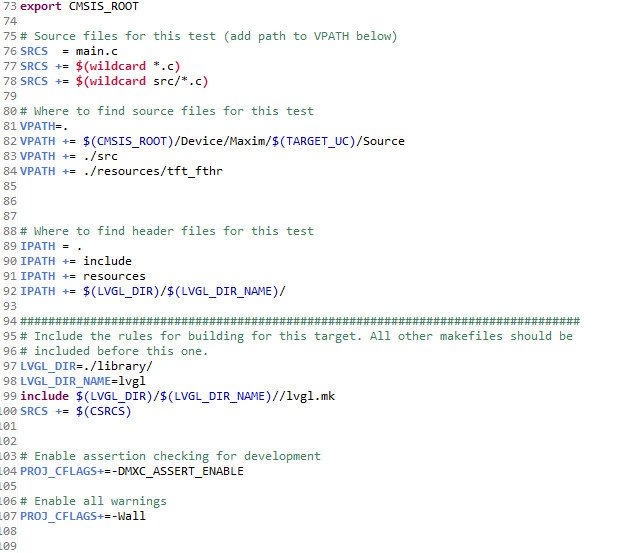
For this purpose, the project's Makefile is also modified as you can see in Figure 39. This will allow our project and the LVGL to be built and linked.
For the LVGL to be able to put data on our display, the driver must be able to transfer a chunk of image data. While the provided display driver can write pixel by pixel data to given positions, the overhead generated will be very high. A quick way is to send a rectengular image to the display. This is implemented for the camera driver, but the way the data is expected in this function is not compatible with the way the LVGL generates its display data. Modifying the display driver with a function to process data the way the LVGL produce them was not that hard. And while the code was running, it was submitted to the MAX78000 SDK repository as pull request [4]. This way you don’t need to change the SDK files, and everyone can benefit from the work done. This way the SDK and other parts can be improved.
Put All Parts Together
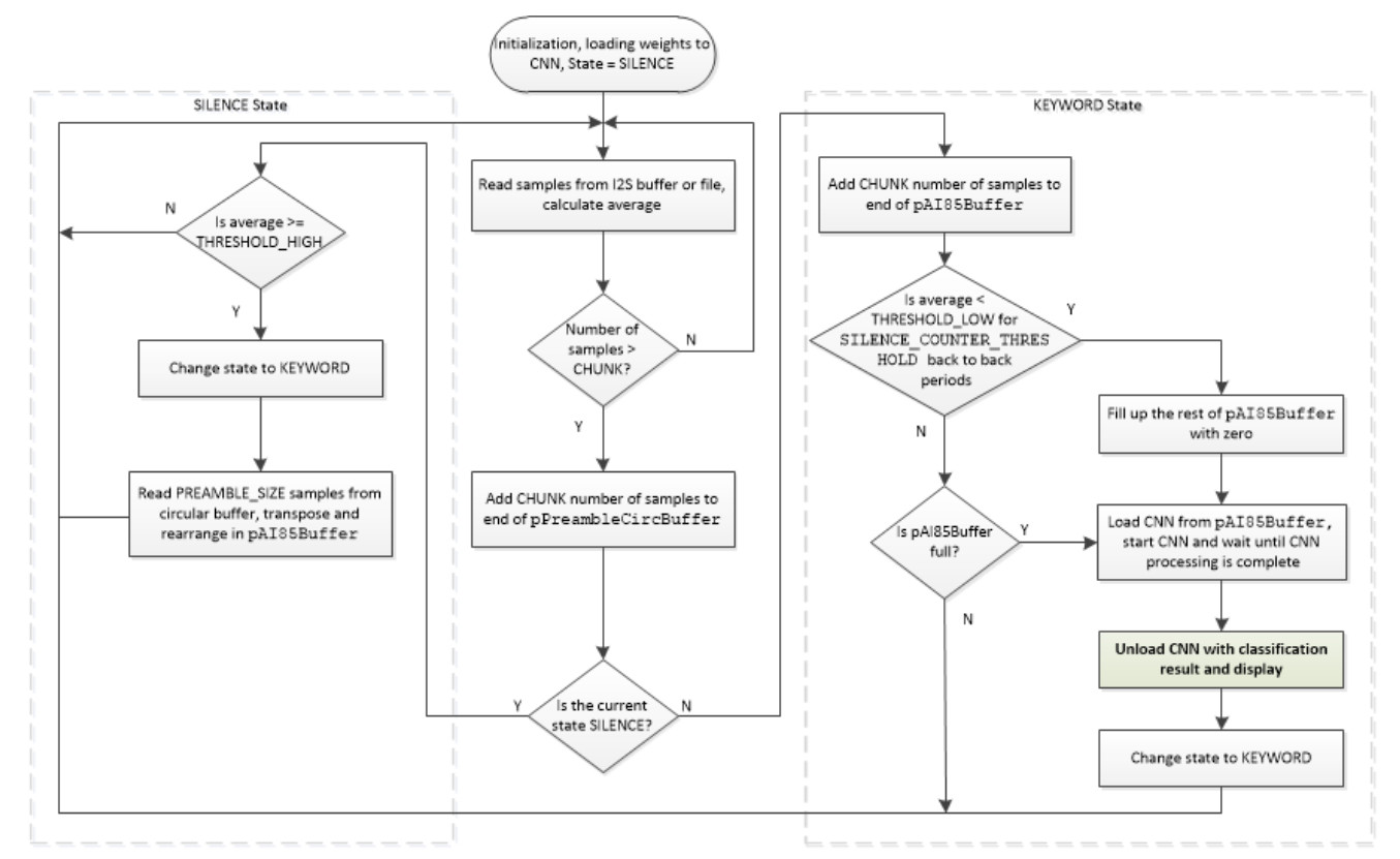
We now have a GUI library that can operate with the MAX78000 and we can detect keywords, so only the logic is missing. Before we continue, we need to look at how the keyword-spotting works. Figure 40 shows the original software flow. So, we are intercepting at the recognized keywords and will use them as input for a coffeemaker state machine. This one shall handle the GUI and logic for us. Up to this point, coding was going according to plan.
One thing that is crucial to the keyword spotting is the audio processing. If we use too much time for other tasks, our keywords may not be recognized. This can be due to discarded audio samples if we do not process the input data within a certain timeframe. And this is exactly what happened after the first version of the coffeemaker was tested. So, the first flow seen in Figure 41 can't be used. If we have timing constraints for the audio part, why not moving the GUI to the RISC-V core? It should be more than capable of running the GUI. Also, the LVGL would be well suited to run on that core as it is designed to operate in low power modes.
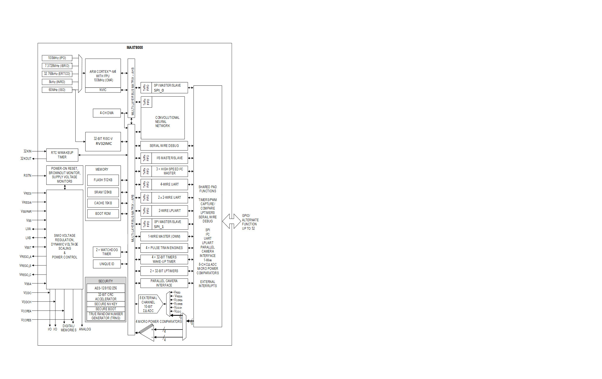
There Is a RISC-V Core
For such tasks, the RISC-V core would be ideal as this one can handle the GUI fine and it offers enough horsepower to all the data generation and movement for the LVGL. Sadly, there is one catch to it. If you read through the user guide for the MAX78000, you will find some hints about what the RISC-V can access. Something that is only indirectly mentioned is the inability of the RISC-V core to access the AHB peripherals like SPI0 or the CNN FiFo. This leaves us with a small hurdle, as the display and some other peripherals like the SD-Card interface and SPI RAM are attached to SPI0. This means for this case, it is not of any help currently to offload the GUI totally from the Cortex-M4 core. Also, as a side note, the on-board debugger is not attached to the RISC-V core, therefore we can only us it to debug code running on the Cortex-M4. We will not follow the dual core road in this article and may leave it for another one. To get a bit clearer view what you can address, see the modified block diagram in Figure 42.
With the currently included dual core example, you also need to be aware that you will lose the ability to do any debugging on the RISC-V core and the Cortex-M4 core. This is due to the way the combined executable is currently generated and should, and probably will be, improved by Maxim in the future.
Make the Coffeemaker Go
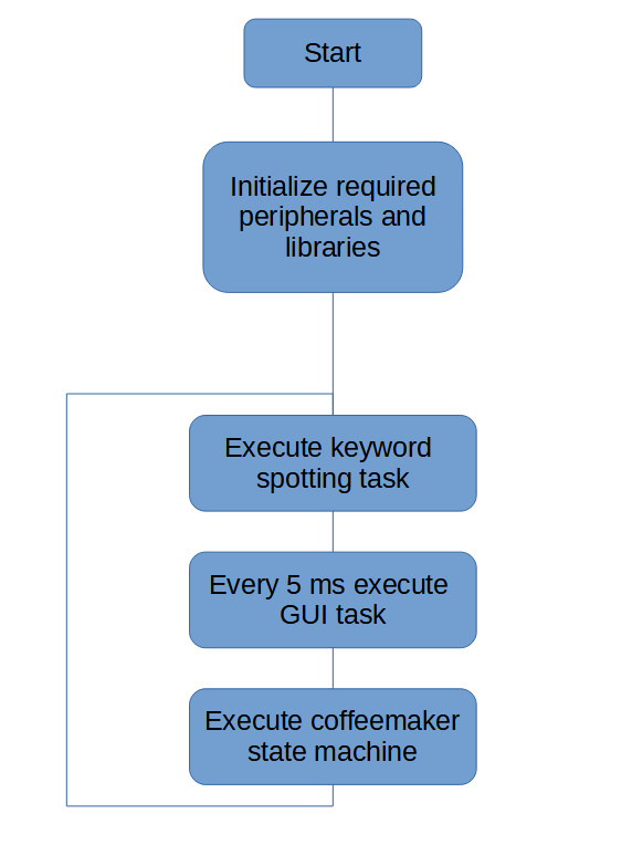
As we cannot use RISC-V, some adjustments to the program flow needed to be done. The new modified flow can be seen from Figure 43.
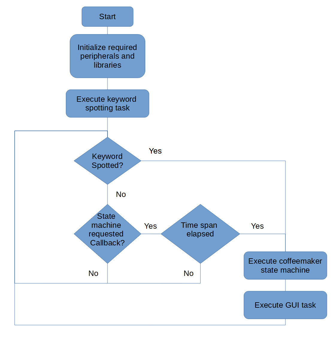
With this flow the GUI is only updated at a point where interference with the audio capturing process will less likely result in lost audio samples. The resulting code can be downloaded from the Elektor GitHub page to get a better look at the mechanics. If you do your own projects, a good advice is to identify the time critical data flow.
The coffeemaker now listens to HAPPY and will ask a few questions before it will brew your coffee. Those questions are simple YES or NO ones, so we utilize only a fraction of the trained word. Also, there is no STOP implemented yet — for example, if your cup gets overfilled. As this is an example, it is far from perfect. To be used in production, it will need a lot more work on the code and the internal dataflow.
A First MAX78000 Project
You can get your first HelloWorld done within a short time. This is also true for a modified keyword spotting demo if you have the right hints. Committing to a MAX78000 and doing AI currently means that you need to deal with documentation that will get enhancements over time. You might find some bugs or missing parts within the SDK. You need to keep in mind that the SDK and documentation is still under construction at some points.
With the MAX78000FTHR, you get an inexpensive tool for entering the world of AI on embedded devices. Maxim did a great job integrating a convolutional neural network acceleration into a chip that can operate on constrained power sources. If you want some tips and tricks, head over to the Elekor Labs pages and use the comments function.
A MAX78000 Design Contest for AI Pioneers
If you like challenges, there is one more for you. You can participate in the Maxim Integrated MAX78000 AI Design Contest (powered by Elektor) for a chance to enter an idea for a MAX78000 use case. Equipped with a MAX78000 board, you can develop a project, share your experience with our audience, and get more experience with AI. This is your chance to be a true pioneer. Take this opportunity to gain knowledge in field where not many embedded developers have coded before, where embedded meets AI. Head over to the contest site — elektormagazine.com/ai-contest-max78000 — for more information. If you have any questions or trouble during the contest, you can also ask one of the Maxim engineers for support. This shall ensure that you don’t struggle with your project’s creation.
Wishes for Future Improvements
A wish for the near future is the documentation of the RISC-V core and more sample code. Also, the inability to access some peripherals form the RISC-V core should be state more clearly, also other limitations with the combination of both cores should get an own chapter within the datasheet. For the code examples, also one wish would be, how to utilize the DMA engine in a very few steps. Even if we cannot access the SPI0 peripheral directly, the DMA unit should. This can give a way to use SPI0 even with the RISC-V core. Also, if now directly part of a user manual, some basic code examples how the Cortex-M4 and the RISC-V need to have interrupt handler written will for sure make it more user friendly. And while Maxim is on it, a dual core HelloWorld, that lets us debug the Cortex-M4 core and run code on the RISC-V core would be a good starting point. For the last wish we already have some ideas our self, but currently not sure if it is the intended way to go. For the IDE, I know this is wishful thinking, but how about integration into platformio for visual studio code? Or at least official Linux support. For the training of our neural networks a Linux system is a preferred way to go, why not also for the software development of the MAX78000?
Take AI to the Max
The MAX78000 offers you a glimpse into the future and brings AI to the world of resource-constrained embedded devices. If you like to use bleeding-edge devices, this one is for you. At just €40, it offers you an affordable point of entry to the field of AI and neural networks. The hardware is surely exciting, but be prepared to tackle some to be enhanced documentation. If you are new embedded development, it might take you a while to get a hang of the MAX78000 and to realize its full potential. But don’t let a good engineering challenge deter you. I am curious to see what Maxim will improve over the next weeks and months. Perhaps we will see improved documentation and added chapter for the RISC-V core.
With a MAX78000, some creativity, and a little perseverance, I am sure many of you will come up with innovative projects in the near future. I encourage you to put your skills to the test by entering your projects in the Maxim Integrated MAX78000 AI Design Contest!
Author's note: While writing this article, I consulted with engineers from Maxim Integrated.
Questions or Comments?
Do you have technical questions or comments about this article? Email the author at mathias.claussen@elektor.com or contact Elektor at editor@elektor.com.
Discussion (3 comments)