
AI with the MAX78000 Feather Board: Hardware Essentials
on
At first sight, it might look like “yet another microcontroller board,” but even though the Maxim Integrated MAX78000 looks like a “normal” dual-core microcontroller, it has features that puts it in a different field of embedded applications — artificial intelligence (AI). In this context, AI is, very simply put, the ability of a system to recognize complex input patterns, like sounds and images, and of course: to implement control systems that can react to these patterns. For example, the evaluation kit presents — among many others — an application to recognize voice commands. And this could be enhanced, for instance, to switch digital outputs according to the command.
The first introduction to the MAX78000FTHR evaluation board was published by my Elektor colleague Clemens Valens. The article I present here will cover the board’s hardware. My Elektor colleague Mathias Claußen will guide you through the first steps of the software development in a separate article.
Rapid Dev with the MAX78000FTHR
The following text from Maxim Integrated’s documentation describes the piece of electronics that landed on our desks a couple of weeks ago:
The MAX78000FTHR is a rapid development platform to help engineers quickly implement ultra-low power, artificial intelligence (AI) solutions using the MAX78000 Arm® Cortex®-M4F processor with an integrated Convolutional Neural Network accelerator. The board also includes the MAX20303 PMIC for battery and power management. The form factor is 0.9” x 2.6” (approximately 25 mm x 70 mm) dual-row header footprint that is compatible with Adafruit Feather Wing peripheral expansion boards. The board includes a variety of peripherals, such as a CMOS VGA image sensor, digital microphone, low-power stereo audio CODEC, 1 MB QSPI SRAM, micro-SD card connector, RGB indicator LEDs, and pushbuttons. The MAX78000FTHR provides a power-optimized flexible platform for quick proof-of-concepts and early software development to enhance time to market.
Artificial intelligence requires extreme computational horsepower, and the MAX78000 is designed to provide to the capability to execute neural networks at ultra-low power: the integrated hardware-based convolutional neural network (CNN) accelerator can execute AI inferences (the use of pre-trained models) at very low energy levels. This brings AI close to (or even: into!) the world of IoT.
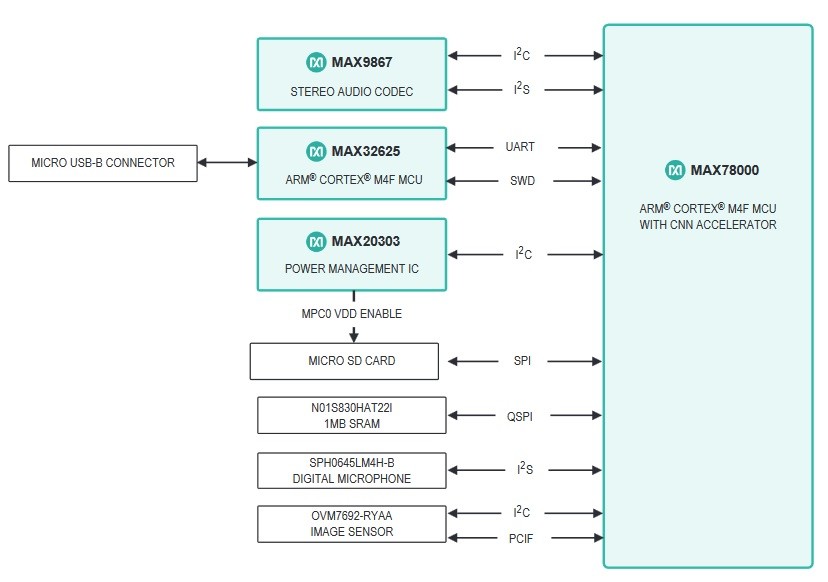
In this article, we’ll have a look at the MAX78000 hardware and the features and peripherals the Feather Board offers. Figure 1 shows a simplified block diagram of the hardware that is incorporated on the MAX78000FTHR board that will be discussed in more detail here.
The MAX78000 Microcontroller
This controller is of course the heart and the most important component on this evaluation board. Here we will only briefly discuss the main features of this microcontroller. For more information, we refer to the datasheet that can be downloaded and the MAX78000 User Guide that — at the time of writing — can only be found on GitHub; but soon it will most probably be available on Maxim Integrated’s website too. Figure 2 illustrates the structure of the hardware blocks inside this microcontroller.
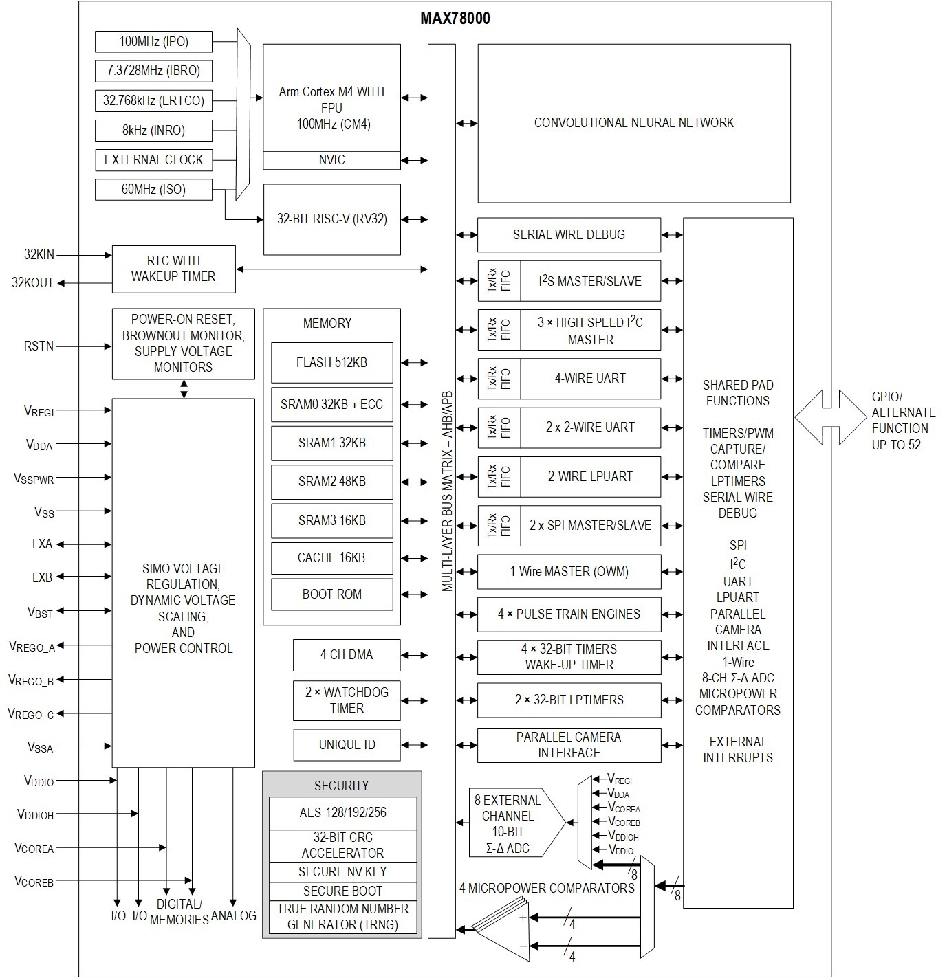
The MAX78000 is a dual-core device, with an Arm Cortex-M4 Processor with FPU able to run at 100 MHz speed, and a 60 MHz RISC-V Coprocessor. The first is responsible for most of the control and processing in the MAX78000, while the RISC-V Coprocessor is added for auxiliary tasks, like DMA data transfer and background tasks, such as GPIO processing. In general, the processors have equivalent access to system peripherals and can be programmed for arbitrary tasks. The internal memory available to the microcontrollers for general use in the MAX78000 consists of 512 kB Flash, 128 kB SRAM, 16 kB cache and Boot ROM.
The Convolutional Neural Network (CNN) block at the upper right of the block diagram is the most important block where AI is concerned. Discussion of artificial intelligence, as well as information on how this CNN block works, is beyond the scope of this article, more information on the CNN can be found in the datasheet and the User Guide. The CNN block contains dedicated memories for neural network weight storage and for input data storage and processing. These memories are independent and in addition to the memories just mentioned available to the microcontroller.
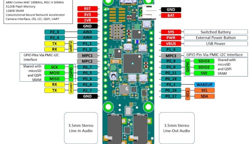
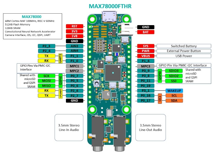
Internal clock and power management can be used to balance computational performance and power consumption of the MAX78000. The MAX78000 has up to 52 general-purpose I/O (GPIO) pins, which are shared with an impressive collection of interfaces. Of course on the MAX78000FHTR board, many of these pins and interfaces are occupied by the on-board hardware and peripherals. Even pins routed to the expansion connectors at the sides of the Feather Board may be shared with this hardware, always check if external electronics you want to use may conflict with the board and the firmware you are implementing! The illustrations in Figure 3 show which I/Os are used for the on-board peripheral components. The output voltage of each MAX78000 GPIO pin can be configured in software to be at either 1.8 V or 3.3 V logical level. (Figure 3 shows peripherals on the Feather board, connections to MAX78000 and PMIC. Source MAX78000 FTHR Application Platform)
As far as interfaces are concerned, the MAX78000 provides serial debugging (SWD), one I2S (master/slave), three high-speed I2C masters, one 4-wire UART, two 2-wire UARTS, one 2-wire Low Power UART (LPUART), two SPIs (master/slave), one 1-Wire master, and a 12-bit parallel camera interface (PCIF). On top of that, there are eight 10-bit Sigma-Delta ADC channels and three pulse train engines. And finally, a real-time clock and two watchdog timers are provided, as well as four 32-bit timers and two 32-bit low-power timers.
MAX20303 Wearable PMIC with Fuel Gauge
This power management IC incorporates voltage regulators, a battery charger and fuel gauge to control and monitor the state-of-charge of an (optional) external Li-Ion battery connected to JST-connector J9. It is designed for ultra-low-power wearable applications and is configurable through an I2C interface, on this board connected to P0_17 (SDA) and P0_16 (SCL) of the MAX78000. More information on this PMIC can be found in the datasheet.
The MAX20303 controls the power supplies for the Feather Board and automatically switches to the external battery (if connected) when USB power is switched off. The battery is charged by powering the Feather Board via micro-USB connector CN1 if the power required by the system is less than the input current limit; under this condition the battery is charged with residual power from the input, with a maximum of 51 mA of charging current. If processing requires more current than the USB supply can deliver, the external LiPo battery (if available) will be switched on for additional power.
One output of the MAX20303 (L1OUT) can be configured to switch the power supply of the on-board microphone, and a second output (MCP0) can control the power of the SD card socket. Thermistor RT1 is also connected to the MAX20303, most likely (but not documented in the MAX78000FTHR datasheet) to monitor the battery’s temperature during the charging process. It would require the Li-Po battery to be attached to the bottom side of the PCB; RT1 is located close to the triangular pin 1 marking of the SD-card socket.
Debugging and Programming Interfaces
A MAX32625 microcontroller (U2) is pre-programmed with DAPLink firmware, allowing programming and debugging of the MAX78000 ARM Cortex-M4 core via USB. U2 also provides a bridge between one of the MAX78000’s UARTs and USB, so any terminal program running on your computer can be used to exchange serial data with the Feather Board. It also provides the interface to program the MAX78000 as a USB mass storage device, by simply dragging and dropping a binary file.
J1 is a standard 10-pin JTAG connector for programming and debugging the RISC-V core of the MAX78000. Right next to it on the PCB is a footprint for J2, a 10-pin SWD-connection (not mounted) for the ARM-core of the MAX78000. On the bottom side of the PCB you’ll find J3, which is a 10-pin needle adapter connector for the SWD-interface of U2, the microcontroller for the DAPLink interface.
Breadboard-Compatible Headers
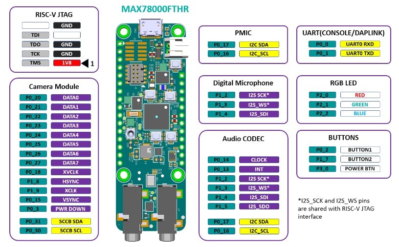
Two SIL-connectors on the sides of the board (J4 and J8) allow the MAX78000FTHR-board to be plugged into a standard breadboard and the footprint of the PCB and these two connectors are also compatible with Adafruit Feather Wing peripheral expansion boards. Figure 4 shows which signals are routed to the pins of the expansion connectors, but keep in mind that some of these signals are shared with on-board peripherals!
Most of the I/O pins on these connectors are directly controlled by the MAX78000, but some of them are connected to the MAX20303 PMIC, which — in that respect — also serves as I/O expander. Note that while all efforts have been made to follow the Feather Wing footprint, this remains an unofficial standard — always check before connecting additional Feather Wing boards to make sure there are no electrical or logical conflicts.
The levels of I2C lines on pins 11 and 12 of J4, are shifted from the on-board 1.8 V to 3.3 V with level shifter U6 (a MAX14595), this can be switched back to external 1.8 V levels by swapping the zero-ohm resistor from position R15 to R20 on the bottom side of the PCB, close to pin 12 of connector J4.
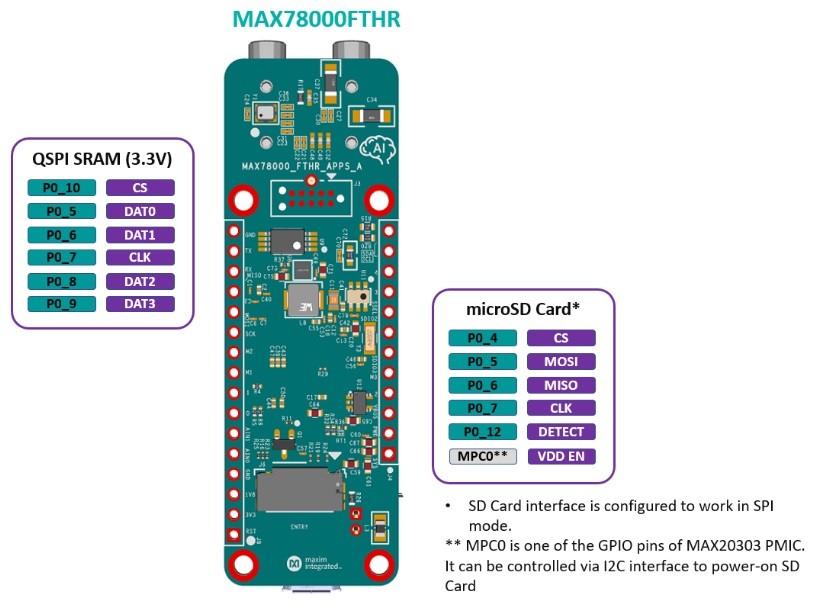
Micro SD Card Connector
J6 on the bottom side of the PCB, is a standard micro-SD card socket. It is connected to the MAX78000 via an SPI interface, the power supply of the SD-card can be switched with output MCP0 of the MAX20303 Power Management IC and a MOSFET. The SPI interface is shared with the on-board QSPI RAM.

Have an idea for interesting MAX78000-based artificial intelligence-related project? Check out the Maxim Integrated MAX78000 AI Design Contest (powered by Elektor).
RGB Indicator LEDs
The MAX78000FTHR board contains three RGB LEDs. D1 is available for user applications, with the red, green and blue LEDs connected to P2_0, P2_1 and P2_2 of the MAX78000 respectively. D2 is wired to the MAX20303 PMIC LEDx outputs, which can also be configured as charge status indicators using I2C commands. DAPLink adapter status LED D3 is controlled by the programming/debugging interface and cannot be controlled by user applications.
Pushbuttons
Of the five miniature pushbuttons on the board, two are available for user applications: SW1 and SW2 are connected to the MAX78000 pins P0_2 and P1_7 respectively, via dual debounce IC U11, a MAX6817. SW3 is the power on/off pushbutton, that powers the MAX78000FTHR board off if the button is pressed and held for more than 12 seconds and immediately switches the board on when pressed again. This switch is wired to the MAX20303 PMIC’s PFN1 pin. SW4 is the MAX78000’s reset button, and SW5 enables firmware update of the DAPlink Debug and Programming Interface MCU (U2).
CMOS VGA Image Sensor
This VGA sensor can be used for image and pattern recognition applications. The Omnivision VGA CameraCubeChipTM color CMOS sensor OVM7692 U1 is directly wired to the MAX78000 via its Parallel Camera Interface (PCIF). Note: the sensor can still be covered with a protective film on the lens after unpacking, do not forget to remove this before using the camera!
Audio
Two 3.5 mm stereo jack connectors (J5 and J7) allow connection of stereo line-in and line-out signals respectively for sound processing. The signals are routed to a MAX9867 low-power stereo audio CODEC, which is controlled by the MAX78000 via I2C, while the digital audio data are transferred between CODEC and microcontroller via the I2S bus.
This I2S bus is shared with MK1, an SPH0645LM4H-B digital microphone manufactured by Knowles Acoustics. To prevent conflicts on the I2S bus with the CODEC, the power supply of the microphone can be controlled via I2C by PMIC output L1OUT.
External SRAM
On the bottom side of the PCB, U2 (N01S830HAT22I from On Semiconductor) provides 1 Mb additional QSPI SRAM. This serial interface for this memory is connected to pins P0_5 to P0_10 of the MAX78000, some of these pins are shared with the SD card interface.
A Powerful Solution
With this MAX78000 Feather Board, Maxim Integrated presents a platform for battery-powered AI applications that is small in terms of size, but big in terms of processing power and peripherals, and its Adafruit Feather-compatible footprint allows easy connection to other hardware. With a retail price around €25 for the MAX78000FTHR, you’ll get a development platform with great peripherals that can also be of service if you want a powerful microcontoller board without needing or using the AI features.
But of course, with a microcontroller board nothing works without software, and the article from Mathias Claußen that will follow soon will guide you through setting up development tools and compiling applications. But for starters, you can play with the pre-programmed keyword recognition application, that demonstrates what this AI board can do!
Discussion (8 comments)