
Battery Management
on
So, what is it about lithium batteries that, unlike other common battery technologies, results in this demand for electronic battery management? This article takes a look at that question and shows how it is dealt with.
Non-lithium cell technologies
Lead acid: The beauty of the old lead-acid batteries is that they can be safely charged by simply applying a DC voltage to the battery pack. Each cell requires a voltage source in the range of 2.15 to 2.35 V to charge. A 6-cell 12 V battery therefore needs a DC supply in the range of 12.9 to 14.1 V. As the cell voltage rises during charging, the current through the battery decreases as it reaches its Maximum Charge Voltage (MCV).This type of battery is very tolerant to overcharging; at worse it may vent some hydrogen. If one of the cells in a battery pack has a little less capacity than the others, you can still charge the remaining cells to the appropriate MCV. They can tolerate a certain amount of abuse provided the cell voltage is not allowed to fall too low. They are so robust that a standard 44 Ah car battery can last for years without any maintenance while being fed from a 55 A alternator and relatively crude regulator…that’s pretty impressive.
A lead-acid cell should not be discharged below 1.8 V which means a car battery will be damaged if its voltage falls below 10.8 V. The self discharge rate is about 5% per month, so it’s important to keep a motorbike battery charged if it’s not used during the winter months.
Nickel cadmium: Round-cell NiCd batteries were once a popular rechargeable replacement for the zinc-carbon batteries used to power consumer electronics devices. In the meantime, production of this type of battery has been banned in the EU for more than 10 years because of the high toxicity and environmental pollution caused by the heavy-metal cadmium used in this type of cell. NiCd batteries have fallen out of favour and production is unlikely to be resurrected.
Out of interest, NiCd batteries are able to handle high currents and tolerate many charging cycles. They were a popular choice for radio-controlled cars and the first cordless power tools. The nominal cell or mid-point voltage of a NiCd is 1.2 V. The method used for charging is similar to that of the lead acid battery but they have an MCV of 1.5 to 1.57 V per cell (depending on the current). Deep discharge below 0.85 V per cell damages the battery, even though it is generally much more robust than a NiMH or lithium battery. Self-discharge in this type of battery amounts to something like 20% per month. A series connection of these cells when charging is not an issue — therefore hardly any battery management is required.
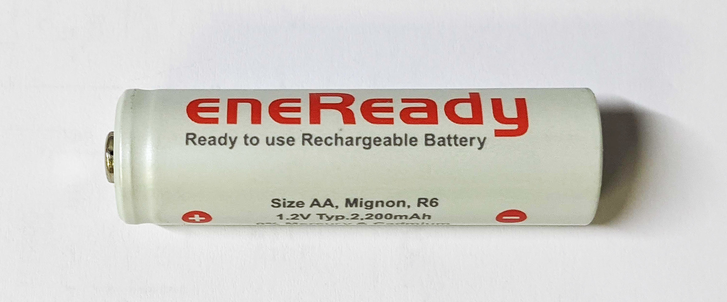
Nickel-metal hydride: The small NiMH cells available in AA format as shown in Figure 1 have largely replaced NiCd batteries as a non-toxic alternative.
They were the standard choice to power cordless tools due to their low price and easy handling. Larger capacity cells are also available and are used in the Toyota Prius which was the first mass-produced hybrid vehicle. Models II and III of the Prius carry a hefty NiMh battery pack weighing almost a hundredweight.
This pack has a capacity of 6.5 Ah at 200 V. Charge and discharge characteristics are carefully monitored and utilization of partial battery capacity helps promote a long lifetime and supports a high number of recharge cycles. Figure 2 shows the internals of the battery pack from my own Prius II.
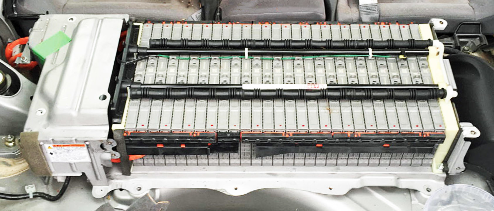
Lithium cells are now the preferred energy storage medium for most plug-in and newer hybrid models now that early teething problems associated with the technology have apparently been resolved.
The self-discharge of NiMH batteries is (usually) comparable to that of NiCd types. However, there are variants like the battery in Figure 1 that have a much lower self-discharge of around 1.5% per month but at the expense of the energy density. These batteries are always preferable for use with gadgets that are used infrequently, as deeply discharged NiMH batteries become unusable.
Lithium: Lithium-based batteries are increasingly replacing all other types of batteries in most mobile and cordless-device applications. They can supply high levels of power and have good energy density. They also have an extremely low self-discharge rate of around 5% per annum. However, as we know there is no such thing as a free lunch and this is reflected in Li-ion (lithium-ion) batteries' high sensitivity to overcharging and deep discharge conditions. Not only can this type of abuse cause them to permanently lose capacity, some have been known to rupture or even burst into flames. These types of cells also suffer at low temperature as their available capacity decreases. Full capacity returns when the cell warms up, but this is of little consolation to drivers of electric vehicles during winter. The properties of Li-ion batteries also degrade at high temperatures.
Due to their sensitivity to overcharging, caution is advised when connecting them in series to achieve higher voltages. Additional charging electronics are required here in the form of a 'charge balancer' that prevents individual cells with a slightly lower capacity from being overcharged when other cells in the pack are not yet fully charged. To ensure a long lifetime and optimal recharge cycling it should be made clear that Li-ion batteries always require a battery management system or BMS.
What makes things even more complicated is that there is not just one type of lithium battery. Depending on the technology and internal chemistry used, the possible number of cycles, the mid-point or Nominal Cell Voltage (NCV), the Maximum Charge Voltage (MCV), the End of Discharge Voltage (EODV), the maximum discharge current and other parameters will vary. The BMS must be tailored to work with these parameters and, of course, monitor current and cell temperature conditions in each specific case.
Lithium-ion battery packs used to power electric vehicles have sophisticated power management systems to control the battery environment and ensure a long service life. For more basic applications, such as providing power for cordless tools and other domestic appliances, the need for such strict monitoring is not usually necessary. Some mobile smart devices and smartphones typically use a single battery and, therefore, require no charge balancing at all. In such cases the charger will only need to monitor the cell voltage to detect the EODV as well as the maximum charge current.
The smaller Li-ion batteries fall into two main categories that differ mainly in the material the positive electrodes are made from. Some use cobalt, cobalt dioxide, manganese and/or nickel, and aluminum. The most widely used positive electrode material is LiCoO2, which is a layered oxide. Fortunately, the nominal cell voltage of all these types is around 3.6 to 3.7 V, the MCV is 4.2 V, and the EODV is 2.5 V (exception: with LiNixCoyAlzO2 the EODV is 3.0 V). Even though the maximum output current and service life may differ across the range of diverse electrode materials they can, in principle, all be managed by the same management ICs.
One exception to this are lithium iron phosphate (LiFePO4) cells that have the following characteristics: NCV = 3.2 V, MCV = 3.65 V and EODV = 2.5 V. This type of battery offers a high number of charge cycles and a slightly lower energy density. For multi-cell applications you will need appropriate charge balancers for this type of cell. The semiconductor industry naturally offers integrated solutions for both categories to cover various battery pack sizes and load ratings - some ICs are even programmable, switchable for certain parameters, and may even have an interface for a host microcontroller.
Li-ion batteries are available in many different designs. The LiPo (lithium polymer) types are mainly built into mobile devices and laptops because they can be made in a relatively flat package. The term polymer primarily refers to the fact that the LiPos are simply welded into a plastic film pouch instead of a solid housing – therefore, any kinks or punctures to the plastic enclosure must be avoided. There are various round cells, including the particularly widespread type 18650 (ø = 18 mm, length = 65 mm) which, astonishingly, is installed by the thousand as a pack in Tesla's electric cars, with the spaces between the round cells used for temperature management. Figure 3 shows an 18650 cell made in China with an incredible specification: 7,800 mAh is a long way from fitting into the 18650 format.
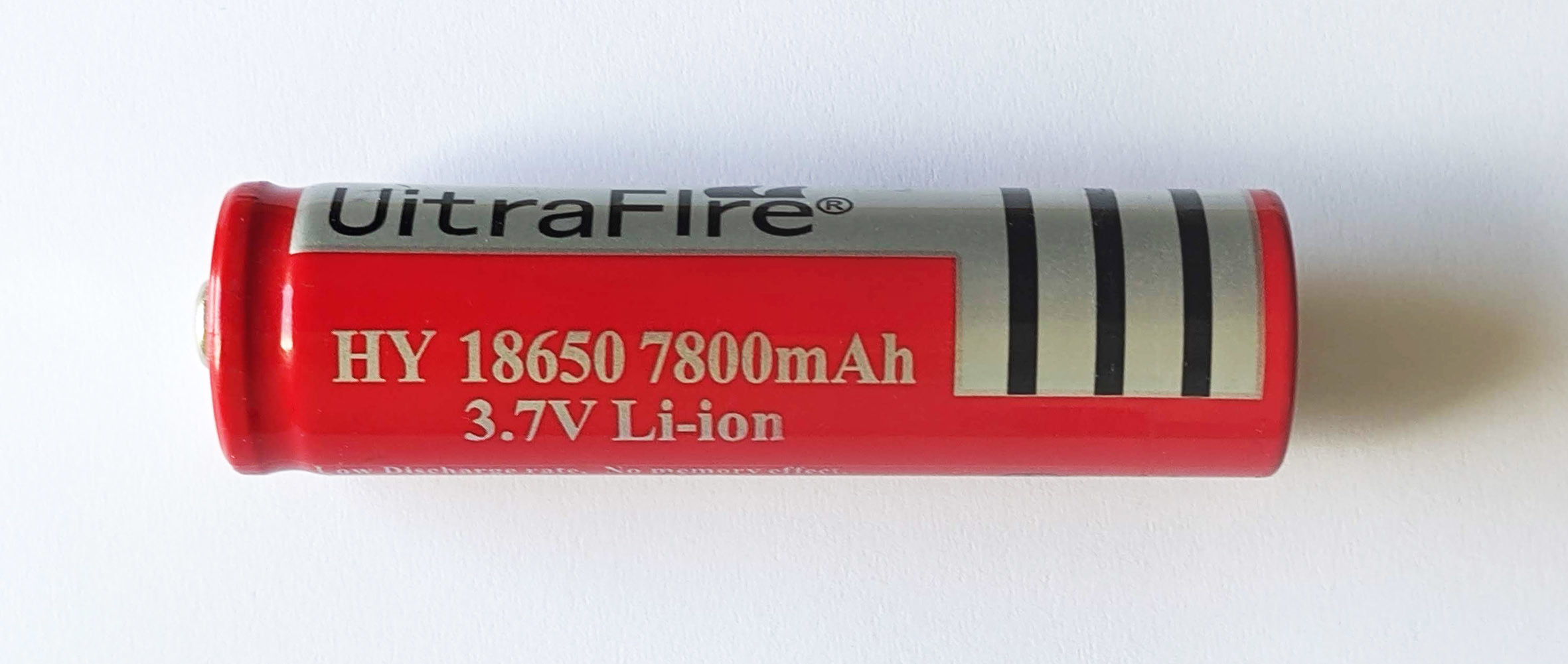
The best cells available today come in at around half this capacity in real terms. Finally, there are the 'prismatic cells', the name of which merely indicates that their housing is not round but cuboid. Such cells were used in the German ‘Hotzenblitz’ mini car manufactured in the 1990s. In Figure 4 you can see that each cell is equipped with electronics to monitor its condition.
A delicate balancing act
The term ‘battery management’ is all encompassing and describes systems that monitor and control recharging, state of discharge, and provide battery protection. Lead-acid, NiCd, and NiMH batteries are fairly tolerant to abuse so their battery management scheme is usually only concerned with details such as MCV, and EODV to control charging and sometimes to limit output current. The situation is more complex when a battery pack is made up of multiple, series-connected lithium cells. Here the BMS must implement a charge balancer.
The main reason for this is that lithium batteries are sensitive to overcharging. Even though mass production techniques ensure uniformity of production, it is inevitable that no two cells will be absolutely identical. In particular, each will have a slightly different energy storage capacity. This means there will always be one weak link in the chain of cells that has the lowest energy storage capacity and becomes fully charged before any other cell in the pack. Given their sensitivity to over-charging, a balancer circuit is essential to cut off charge to this cell before damage can occur. Cell performance also degrades over time so that differences become exaggerated.
A balancer in its simplest form for a two-cell battery pack is shown in Figure 5 monitoring the voltages of two cells.
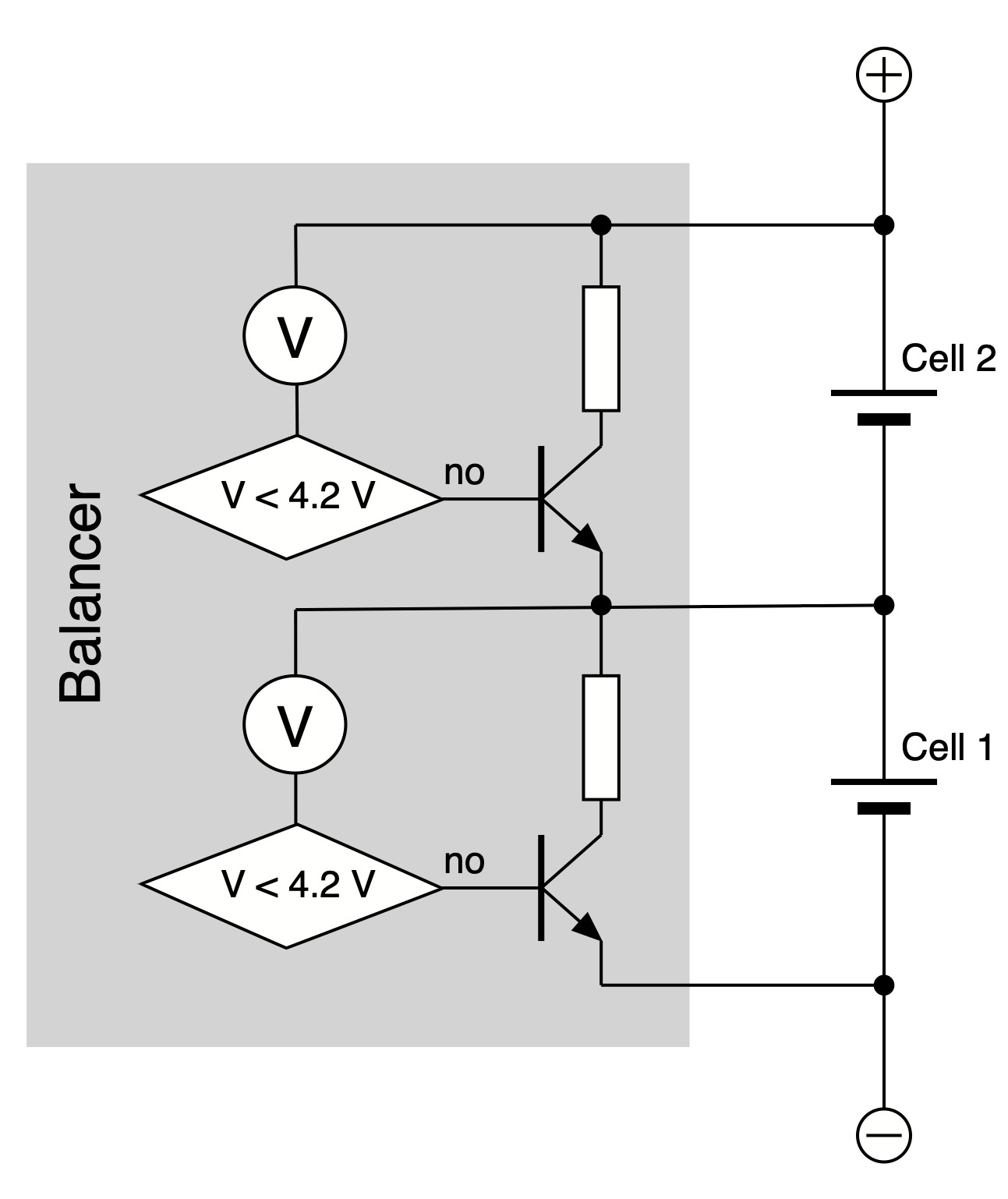
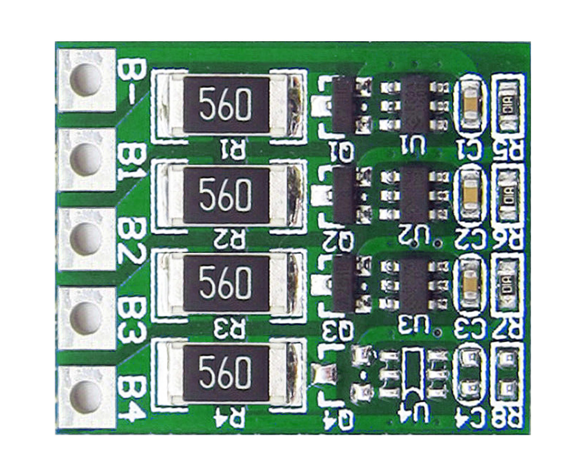
If one of the two cells reaches the MCV, an appropriately small load or shunt is placed parallel to the cell so that the charging current is diverted to the cell that is still charging. If there are more cells, the balancer is scaled accordingly. Figure 6 shows a small BMS board for a four (small) cell pack, available from eBay priced from €1 to €10.
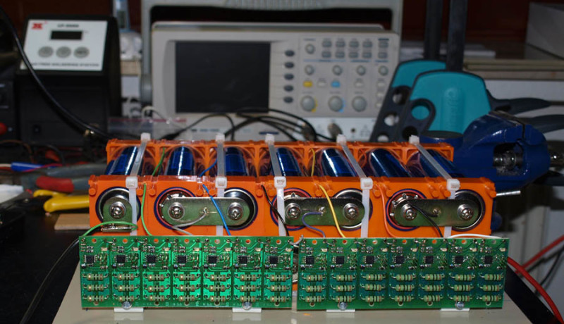
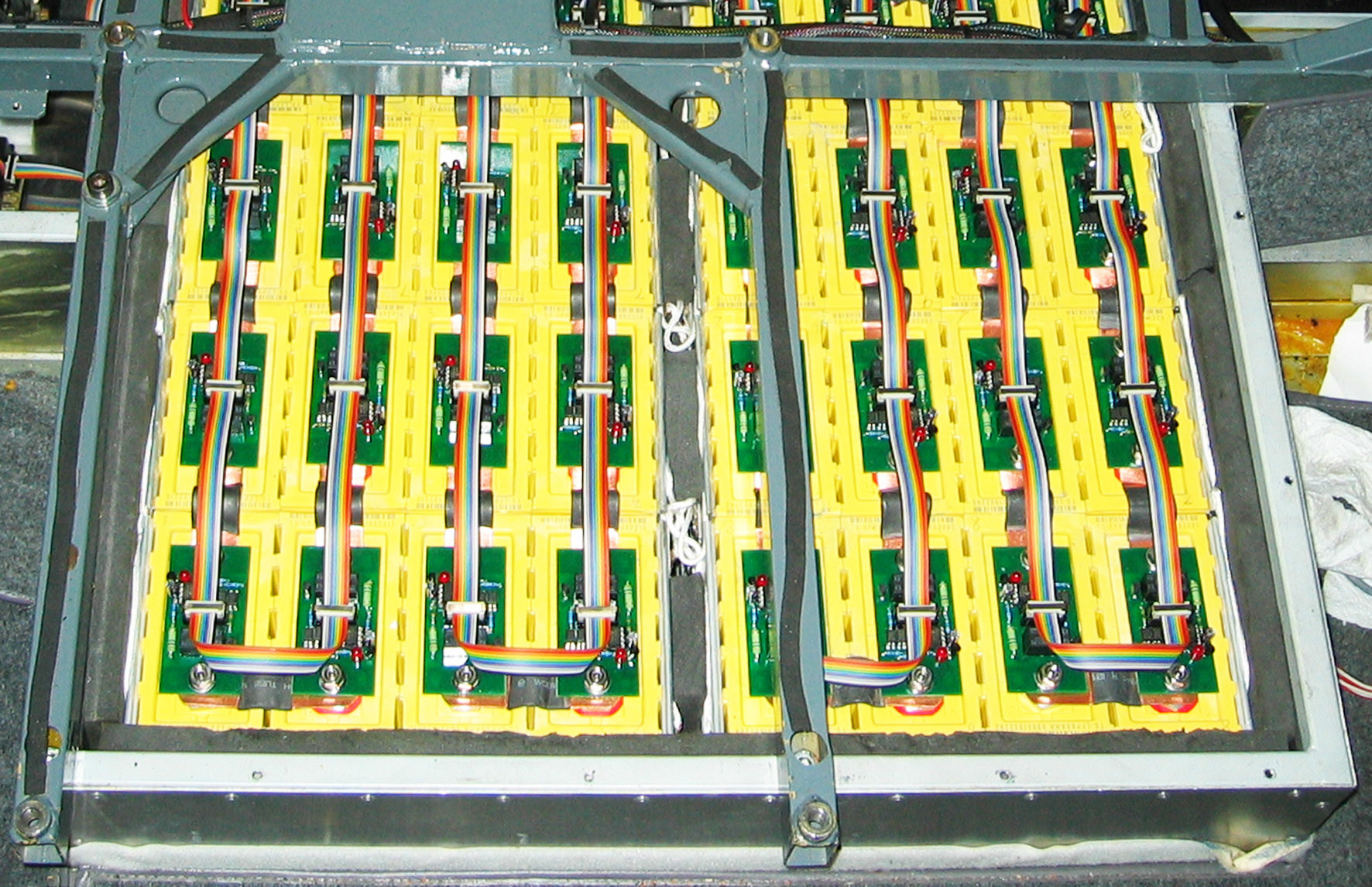
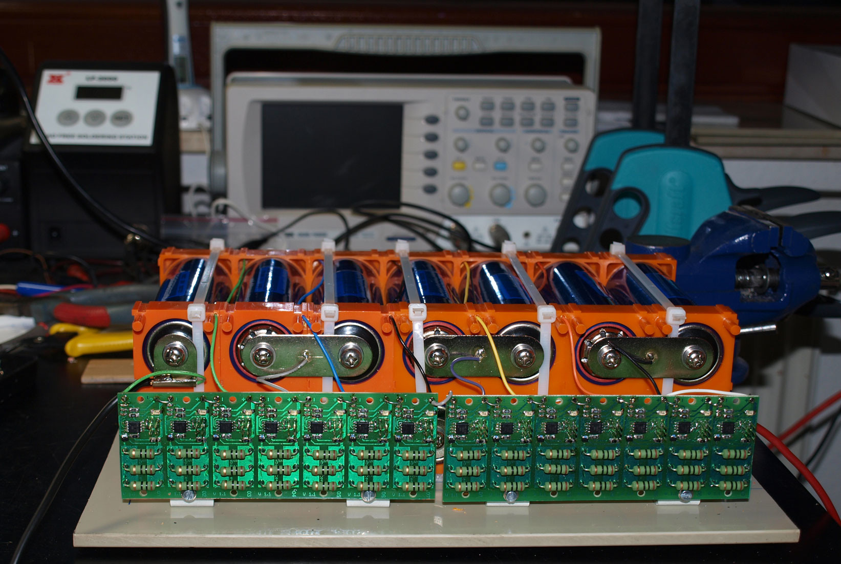
In Figure 7 you can see how much effort went into balancing the 48 V LiFePo battery of my Segway clone. Each cell is monitored by its own microcontroller.
You may think that the shunts look a little underrated for the level of current the batteries can deliver but, in practice, they only need to channel the charging current past the cell to be protected and this is significantly lower than the maximum charging current that can occur. The reason is that Li-ion batteries are initially charged at a nominal current until they reach a state of charge of 50 to 80%. From then on they charge with a small, usually steadily decreasing, current. With LiCoO2 cells the charge current is quite low above 3.95 V. Since the differences between healthy cells are not that great, it is not too troublesome to dissipate this significantly lower current level. In practice, shunts to handle around 1 to 5% of the maximum charge current are almost always sufficient. If it is not enough, it is usually an indicator that a particular cell is no longer usable.
Depending on the current level, energy is dissipated by the balancer circuit, which is quite wasteful. There are special balancing circuits available that can make use of the excess energy by feeding it back into the overall system via a step-up switching regulator (per cell!).
Another important criterion is cost: balancers use electronic components and ICs that are expensive in high voltage versions. Modern BMS ICs are typically available for packs of 2 to 12 cells. With 12 cells you already have an operating voltage of around 50 V. If you want more cells in a battery pack, you simply scale the BMS electronics. With the 800 V systems of modern electric cars, the pack can consist of 20 modules using 12s BMS ICs in series (12s denotes a battery pack containing 12 cells connected in series). The individual subsystems communicate with one another via a (electrically isolated) bus and then to a central controller.
ICs
There are already a wide range of BMS solutions from various IC manufacturers available, too many to provide a comparative overview in the space available here. Instead we will take a look at a specific IC and associated circuits as an example.
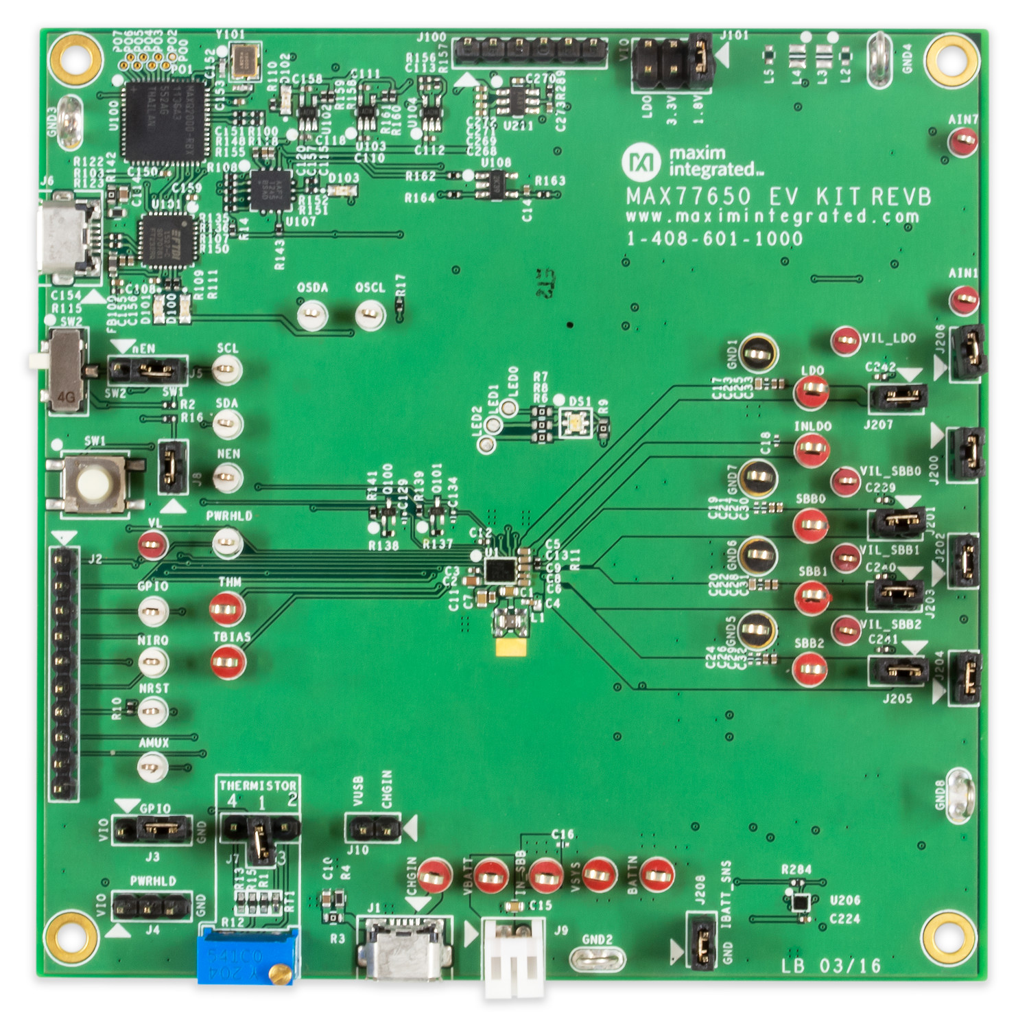
In addition to balancing, a BMS for lithium batteries also has the task of protecting the battery from undervoltage and overcurrent. Sometimes the charging circuit is also included in the system. The use of a microcontroller makes perfect sense for such complex tasks. Modern BMSs therefore sometimes have a small integrated SoC or an interface to hook one up. BMS ICs are available from manufacturers supplying analog ICs or switching regulators, as well as being provided by companies such as Microchip, Maxim (see Figure 8) or Renesas.
The example covered here comes from the latter, which is also well-known for its microcontrollers.
Figure 9 shows the internal block diagram of the BMS IC ISL94212.
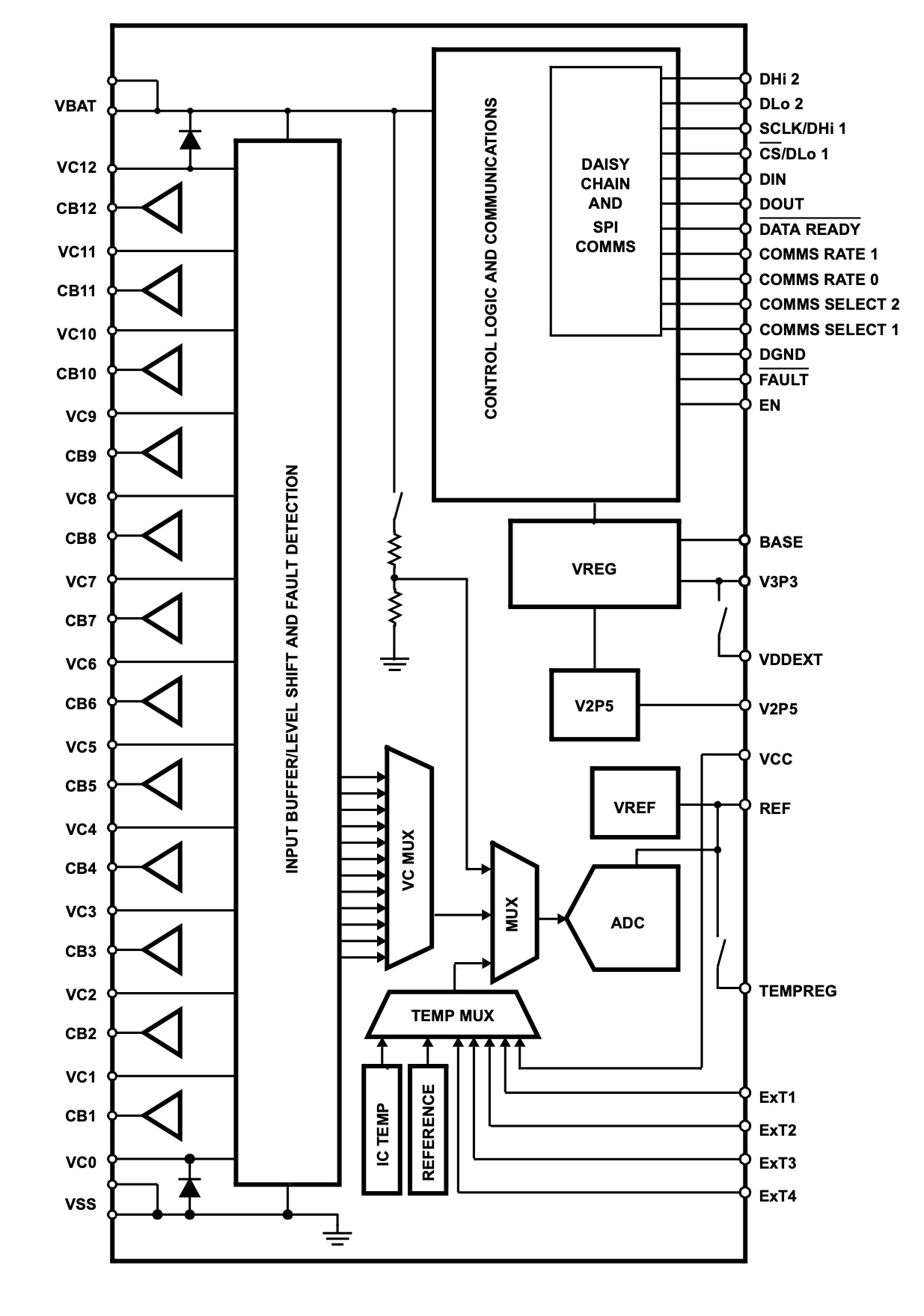
Along the left side you can see the connections for ground (at the bottom) and positive operating or battery voltage (at the top) and the connections for a total of twelve lithium cells. The voltages pass through the ‘input buffer/level shifter’ via two multiplexers (VC MUX and MUX) to an A/D converter. There are also reference voltage generators, blocks for measuring temperature, monitoring of the EODV and, of course, the most important thing, the fully digital block ‘Control Logic and Communications’.
Figure 10 shows a basic application circuit with two controller ICs and 24 cells.
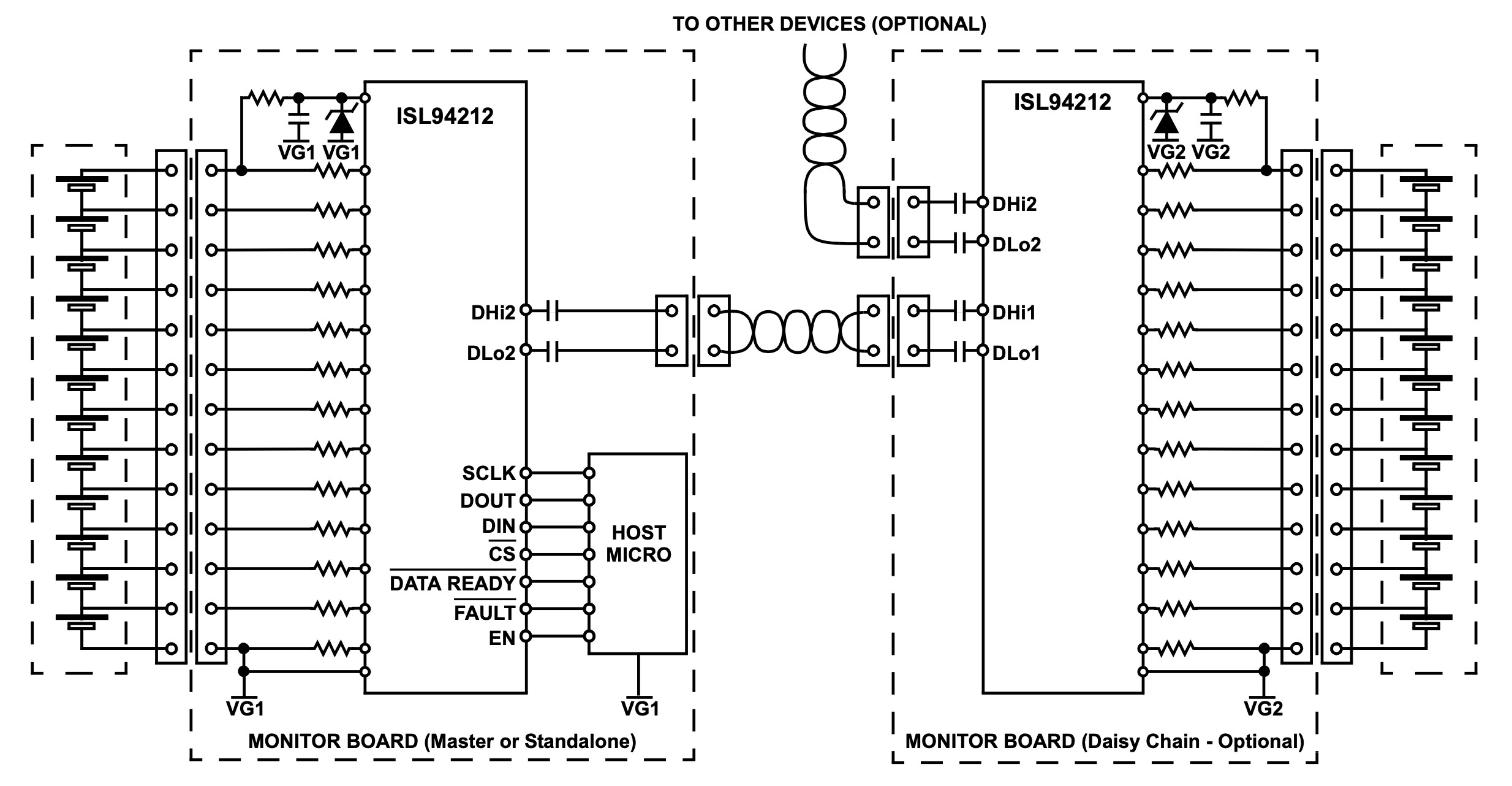
A host microcontroller is shown that communicates with the chip via an SPI interface. Due to the high voltages of such module chains, the serial interfaces are not coupled directly, instead being linked via small capacitors.
The IC not only offers monitoring of many cells but also the required balancing. Figure 11 shows the basic connection of one load resistor per cell (far left) via a small power MOSFET that is controlled via the associated IC output CBX.
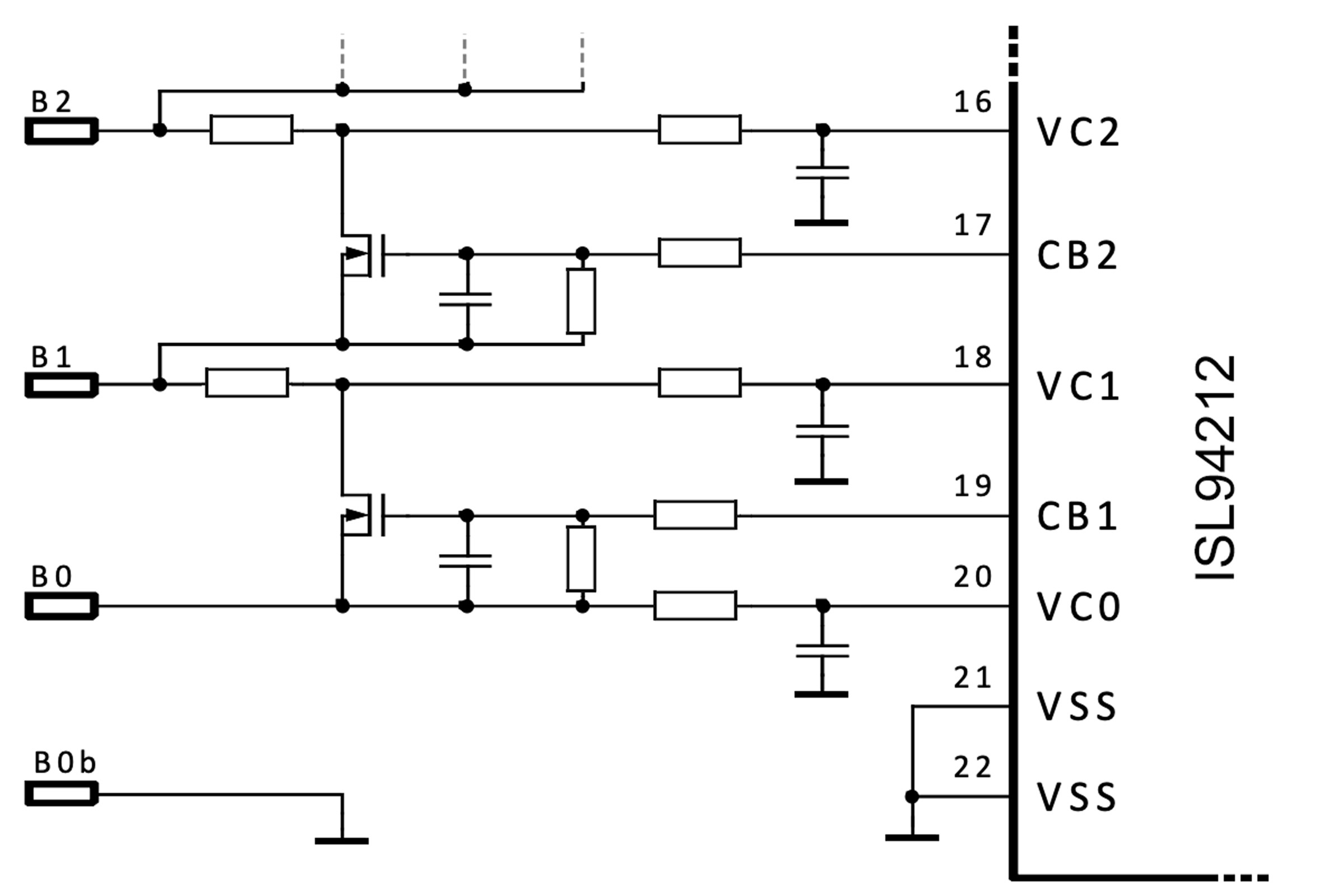
In this way, balancing can also be implemented for very high currents. The details of the many IC functions can be found in the datasheet.
Balancing in practice
If you are dealing with a lithium battery, you basically have a choice of one of three strategies. For simple applications, you can simply buy a small, inexpensive and fully assembled circuit board from a Chinese producer such as the one in Figure 5. If you are planning a larger and/or more expensive battery implementation, you can choose from a vast range of ready-made BMS solutions from the big-name manufacturers. Last but not least, it makes sense to tailor your solution for the battery package in question using one of the wide range of ICs available. In some cases, however, you can and must write your own code for monitoring and controlling the battery if you really want to do it accurately.
Want to learn more about battery management and other topics?
Take out an Elektor membership today and never miss an article, project, or tutorial.
Discussion (1 comment)