
Lithium Battery Pack Repair
on
It’s All Gone Quiet…
Battery-powered equipment running on Li-ion cells certainly retains its performance much longer compared to the NiMH cell-based power tools of the past. However, after many charge/discharge cycles, there comes a time when the energy storage capacity of even the best lithium battery drops so low that the battery pack needs to be replaced. I have already seen this with many of my own devices, and friends and colleagues often turn to me for advice on this topic.The simplest solution is to visit the equipment manufacturer’s website to see if a replacement battery pack is available. Sometimes there isn’t and, when there is, the prices can come as a shock. In my case, the equipment worked just fine and looked to have a good few more years of life in it — a new battery would suffice. In such cases, it can be worthwhile hacking the battery pack and replacing the individual cells when the time comes, which is often cheaper overall. We can even consider improving the performance by replacing the original cells with some of a higher specification. If you also choose this route, you’ll need to fire up the soldering iron in addition to breaking out the screwdrivers.
In my case, I noticed that my Robbi lawnmower only wanted to mow for half an hour before it beetled off to its charging station for a 1.5-hour recharge.[1] Previously, the usual pattern had been an hour of mowing followed by a 1-hour recharge. Was this change in routine a sign? Having had Robbi for four years and knowing it is powered by lithium cells, it was clear that they would likely need replacing.
Later that afternoon, I realized it had been quiet outside for some time. There, in the middle of the lawn, Robbi had shut down and couldn’t be woken by pressing its buttons. I lugged it over to the charging station and put it on charge. Robbi eventually sprang into life, and I read from a menu option that its elapsed operating time was 2,938 hours. Corresponding to almost 1,500 charge cycles, it was clear that I should consider sourcing a new battery soon.
‘Soon’ came earlier than expected. After its full charge, Robbi finished its work, but it didn’t wake up the next morning. Putting it on charge didn’t help either. I had recently treated the lawn with some fertilizer, and we have had quite a lot of rain, so I needed to act quickly. I could almost hear the grass growing…
Hack a Battery Pack?
The manufacturer’s replacement battery pack was priced at around €100, and a replacement from a third-party supplier was available for around half that price, which is not that bad. From its specification, I was looking for an 18 V replacement pack with a capacity of 2.1 Ah. That meant five cells, probably in the standard 18650 outline. To confirm my suspicions, I set about removing the lid of the battery compartment.
Unsurprisingly, this was easier said than done. Three of the screws came out easily, but the fourth was completely jammed. Eventually, it came out, but the captive mounting nut was ripped out in the process, jammed on the screw thread. It looked like it has been cross-threaded during assembly at the factory. Figure 1a shows the captive nut recess in the mower casing after removal. Some debris remained. I eventually separated the screw and nut and, despite part of the captive brass nut breaking off (Figure 1b), it looked repairable.
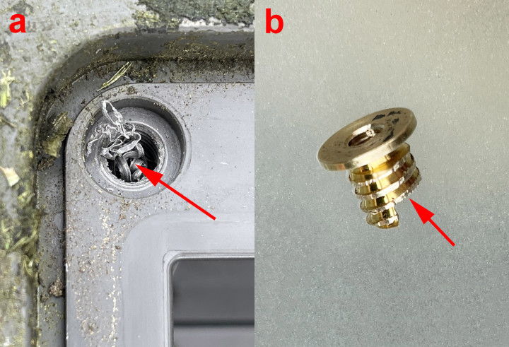
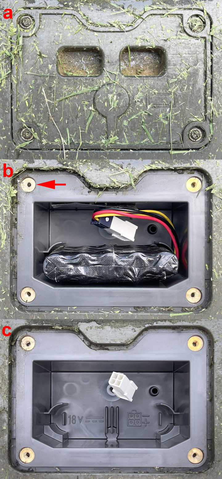
The battery compartment is designed to be waterproof, so the captive nut required remounting to ensure all four screws could be tightened for a good seal. I used an epoxy adhesive to secure the nut, and you can see the result in Figure 2b. The brass nut at the top left looks as if it’s been there forever. With the mechanical part fixed, attention turned to the battery pack. Figure 2b shows the battery in its compartment. The outline of five cells is clearly visible, and a ruler confirmed that they were 18650 cells. There is also a lot of free space (Figure 2c), which got me thinking: could I better use the space by using more or larger replacement cells? My mind was now made up: purchasing an off-the-shelf replacement battery was no longer an option.
Battery Cell Swap
Figure 2a shows that two recesses in the battery lid encroach into the available battery space, ruling out the fitting of two rows of five cells to double capacity. There are, however, more expensive cells in the 18650 format with higher capacity. Some of the better-known brands have cells in this format with ratings of up to 3,500 mAh. Such high-capacity branded cells cost a good 10 € each. You can also find cells with much higher ratings on eBay, AliExpress, and similar sites, but you should take such claims with a pinch of salt.
I almost placed an order for five cells until I noticed some others in the somewhat more unusual 21700 format. Although only slightly larger, they offered significantly more capacity for the money. I was sure they would fit in somehow (I was thinking of a row of three and a row of two to form a W profile). With a quantity discount and postage, the 5 × 4,000 mAh cells came to €26 in total. They dropped through the letterbox two days later, and it wasn’t a day too soon — the grass was now definitely in need of a trim.
Considerations
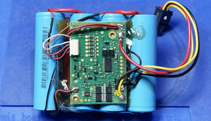
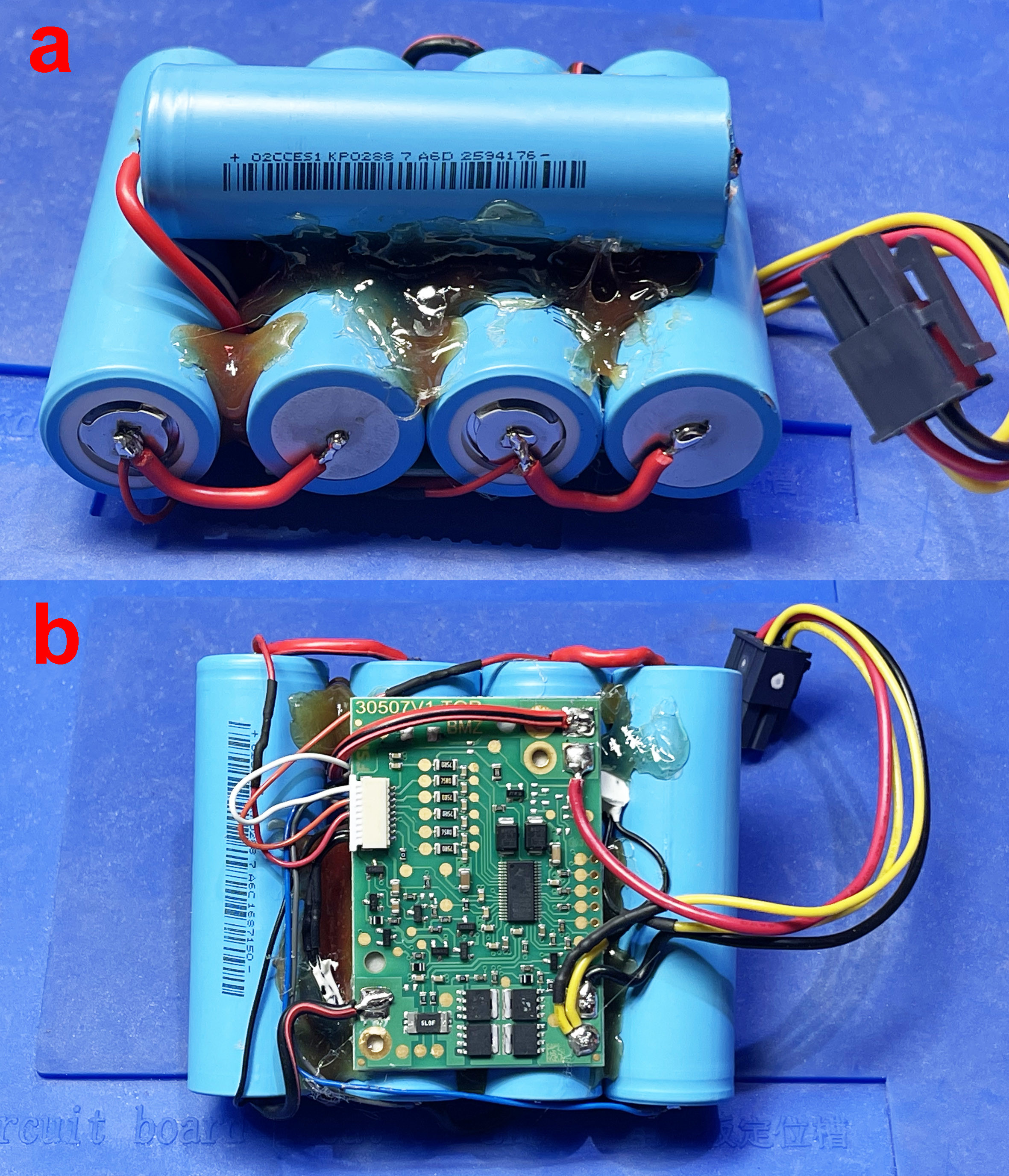
Building a battery pack from individual cells generally requires a degree of dexterity, electrical expertise, and a spot welder. As you can see from the old unwrapped battery pack in Figure 3, the five green cells are neatly connected at the positive and negative contacts via thin, spot-welded nickel strips. This type of permanent connection method does not damage the cell. Although the heat generated during spot welding is intense, it is swift and localized, so the cells are barely warmed. It’s well known you can never have too many tools, but, in this case, I can’t imagine where else I would use a spot welder, so I can’t justify the outlay. Instead, I chose to solder the wires directly to the cell contacts. This is not recommended unless you follow some rules and are aware of the dangers.
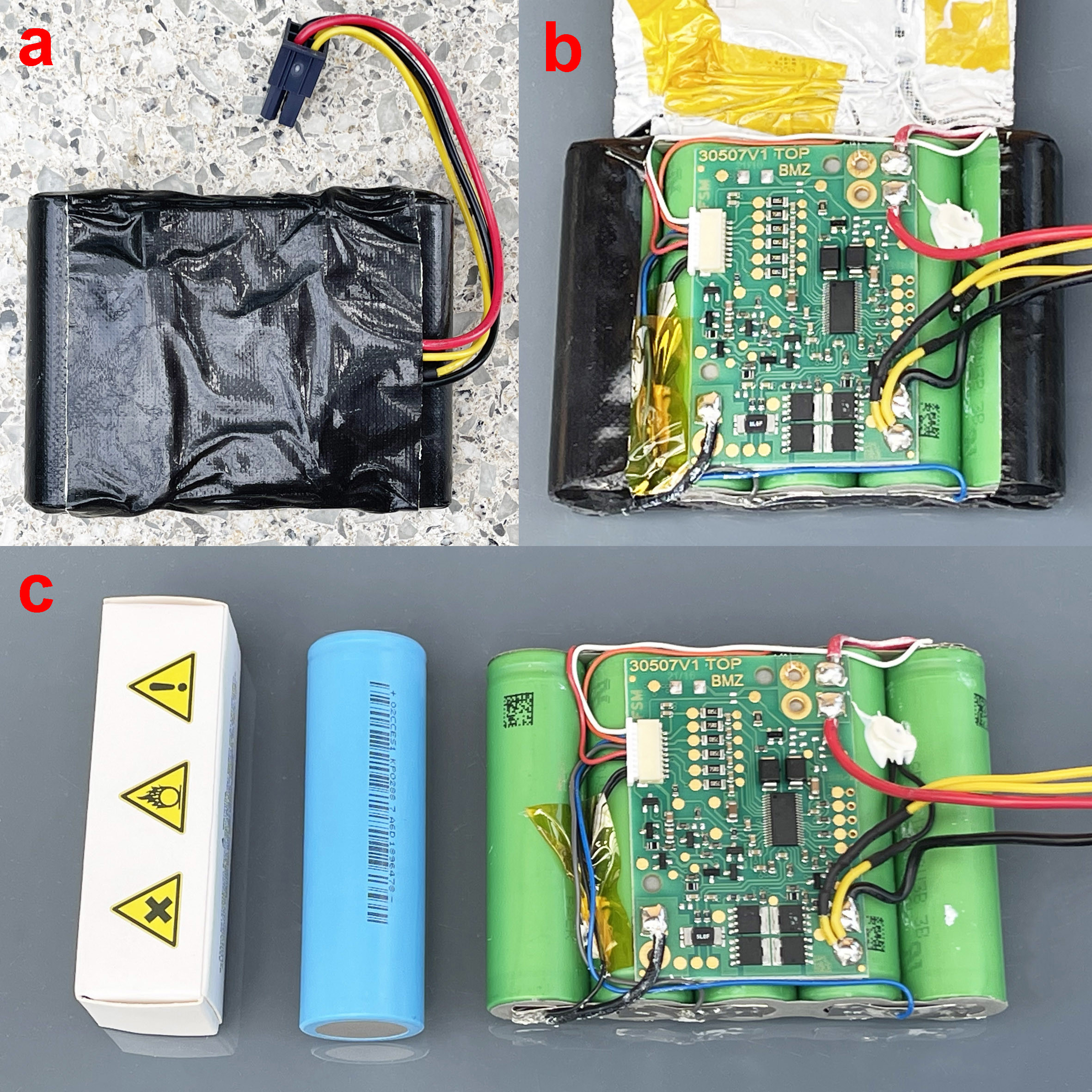
The battery pack used in Figure 3 is typical of that found in many other battery-operated devices. It consists of several battery cells connected in series plus a Battery Management System (BMS) PCB. This is the circuit board shown in Figures 3b and 3c. The latter image also shows a size comparison between the new cells and those in the old battery pack. The BMS performs three basic functions:
- It balances the cells (i.e., keeps them all at the same voltage or charge state).
- It prevents the cells from being overcharged.
- It disconnects the load in the event of undervoltage to avoid deep discharge.
The chip on the BMS board with the most legs manages all these tasks. It is a specialized microcontroller that monitors the cell voltages (via the connector on the left). In the event of an overvoltage or undervoltage condition, it disconnects the cells using 2 × 2 MOSFETs (at the bottom). Further reading on balancing lithium batteries is available under [2] and [3].
The BMS is included if you buy a whole new battery pack assembly, so the BMS board (which still works) from the old pack will be redundant. On the other hand, if you only swap the cells, you can reuse the existing BMS board. An important feature of the BMS that you need to be aware of is described in the BMS Flip-Flop Function section below.
BMS Flip-Flop Function
When I removed the battery shown in Figure 3c, I was surprised to measure 19.2 V directly on the plus and minus contacts of the 5-cell battery pack. Had I been too hasty in ordering replacements? On the other hand, I could only measure about 18.5 V at the battery pack connector where it connects to the mower motor (to the right of the BMS board), which had a very high source impedance. Using just my fingers, I could discharge this to ground, causing the voltage to drop to just a few volts. Was the BMS broken? I connected a 24 Ω load resistor directly to the cell contacts on the battery pack and measured a current of 0.75 A and a battery voltage of 18.2 V. I then disconnected the load and put the pack onto charge. After just a few seconds of charging at 0.5 A, the voltage output from the BMS switched to low impedance mode to draw some current from the battery via the BMS. It looked like the BMS had detected the battery voltage falling below the undervoltage threshold when the mower was last used and had turned off the FET to disconnect the battery. This ‘off’ state had been latched in the BMS. To test it, I connected a 12 Ω load to the battery. After five minutes, the BMS switched off at just over 13 V and switched on again after another charge. Phew… With the BMS good to go, I proceeded with the cell swap.
Keep Soldering On
With no spot welder to hand, I decided to solder stranded wire directly to the battery terminals. As long as you are careful, this can be done without harming the batteries. Any thermal damage inflicted on the constituent materials of the cells is roughly proportional to the integral of time and temperature. In other words, you need to be quick! Three things are important here. Firstly, the soldering iron must be powerful enough for the tip to maintain its temperature during soldering. This ensures that the end of the cell quickly achieves soldering temperature. A solder that melts at a lower temperature is also advisable. I used a 90 W iron as it has a regulator that allows the bit temperature to be set at over 400°C. It is best to avoid lead-free solder for this job as it melts at a higher temperature and does not wet the surface as nicely as the good old SnPb 60/40 that I prefer. In my experience, the metal contact surfaces of the lithium cells take the solder easily. With the tip temperature set to 385°C and using 1 mm diameter, flux-cored solder, I completed each joint in around one second — fast enough to avoid damaging the cell.
If you need to keep the soldering tip on the cell contacts for much longer than this (because the soldering iron is underpowered, the temperature is too low, or through the use of lead-free solder), you risk overheating and damaging the cell. This will impact the cell’s electrical capacity and possibly reduce the number of charge/discharge cycles. As long as the iron is only in contact with the surface for around a second, it shouldn’t cause any harm. Alternatively, you could buy some slightly more expensive tagged cells that come with a short nickel strip already spot welded onto the cell contacts. The strips can then be soldered together to make up the pack without any risk of overheating the cell contents. In principle, this is safer, but you must insulate the bare strips to prevent any short circuit. A short circuit during normal operation will create a significantly more dangerous condition than could occur by applying a short blast of heat to solder wires to the cell contacts.
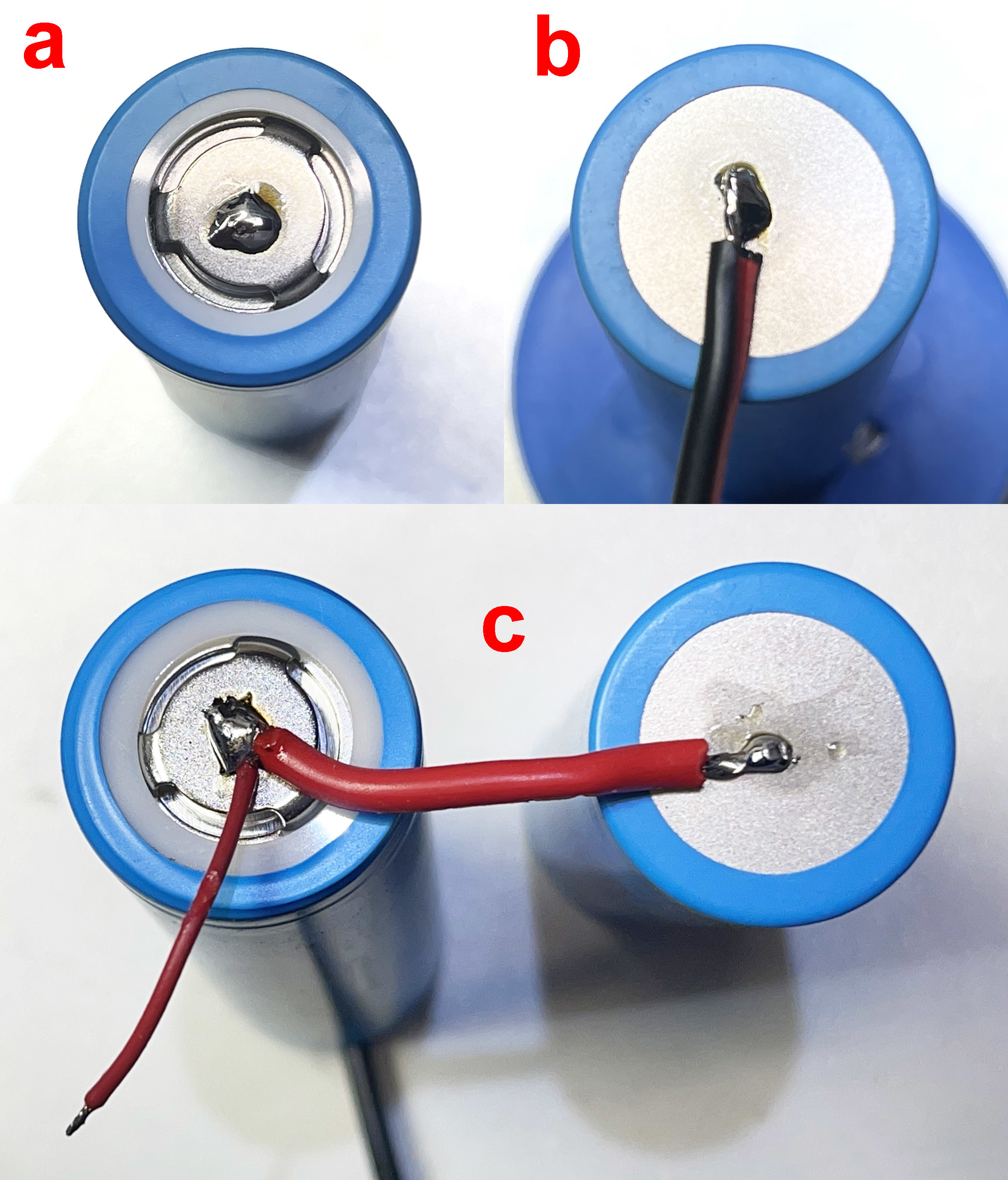
A close-up of my soldering method can be seen in Figure 4. The positive contact consists of a metal cap attached to the battery electrode at three points in this cell. This arrangement increases the thermal resistance between the outside contact surface and the cell’s internal structure, making it more tolerant of the soldering process. Start by applying small drops of solder to tin all the positive contacts (Figure 4a) quickly. Next, cut 1.5 mm2 stranded wire to a length of 3 cm, which allows some leeway for later positioning of the cells in the pack. These can now be soldered directly onto the negative contacts (Figure 4b) in two stages. Firstly, use the soldering iron and solder them quickly to establish a small tinned area in the center of the contacts. Next, strip and tin the ends of the connecting wires. Once the cells have cooled, quickly solder a wire to each of the negative contacts. In Figure 4c, you can see the other end of a wire now soldered to the positive contact of the next cell to make the series connection. The thinner red wire is the cell voltage sense connection to the BMS board.
Assemble and Test
As already mentioned, the battery compartment cannot accommodate the five cells arranged in rows of two and three to form a W configuration, so I had to find a different pack construction. In Figure 5, you can see that four of the cells are placed next to one other and fixed in place with hot glue. The fifth cell is glued across the other four. The hot glue makes the finished assembly very stable. You could alternatively use silicone sealant here.
The double-sided tape on the back of the BMS board did not need to be replaced as it held firmly to the new battery pack. All that remained was to connect the six wires from the white connector (Figure 5b) to the corresponding cell contacts, along with the plus and minus connections of the entire pack, to the BMS board. This must be completed before we can test the new battery. Double-check all the wiring to ensure you haven’t made any mistakes. Taking a photo of the old battery pack will help at this later stage when checking everything. The battery pack functioned as expected and could be charged and discharged without a problem.
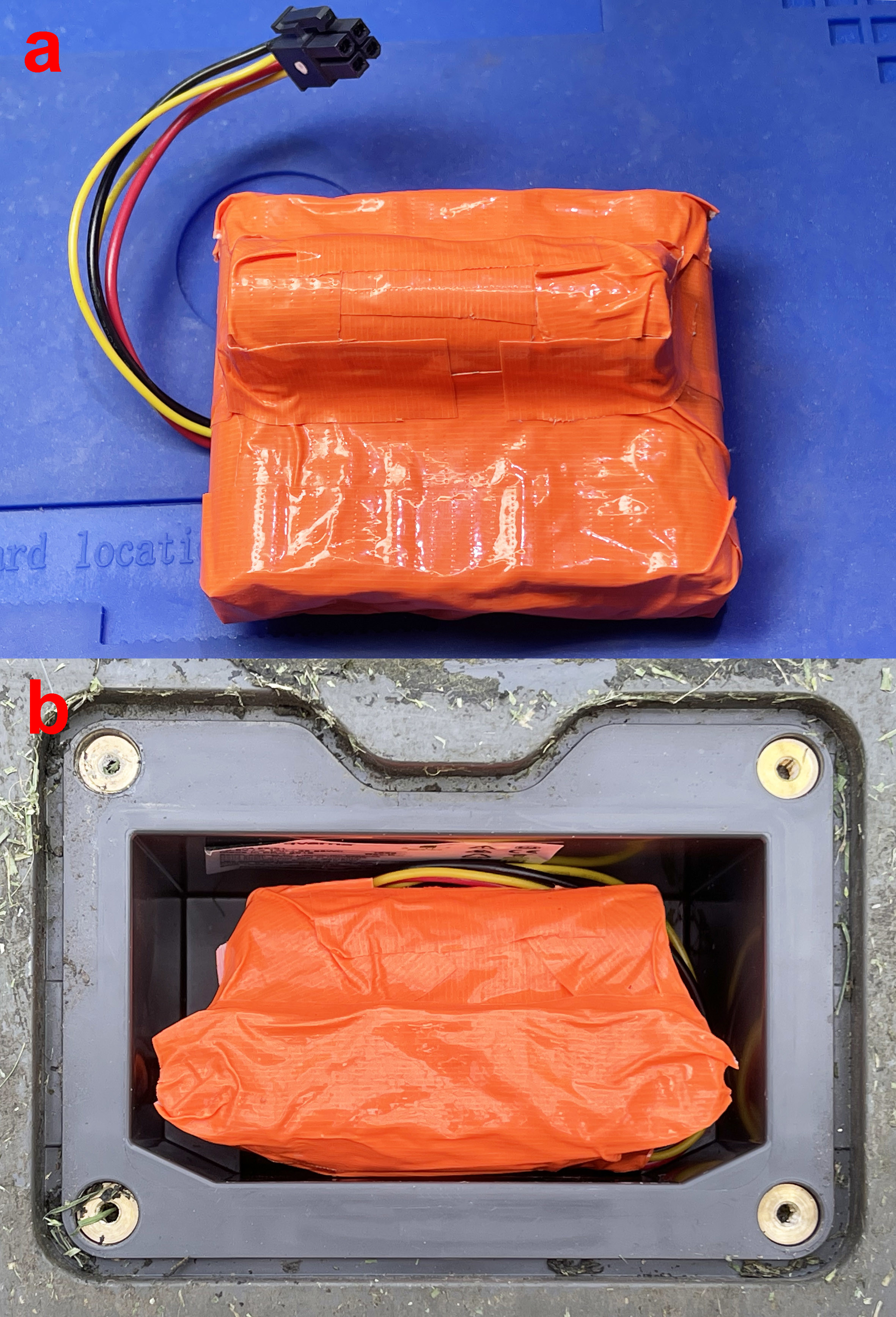
The finished battery pack was wrapped in gaffer tape to make the assembly more robust and provide insulation and moisture ingress protection (Figure 6) before fitting into the mower’s battery compartment. After screwing down the lid and switching on the mower, it wanted to calibrate itself with the signal from the guide cable and to start mowing immediately. I canceled the latter operation and put it into its charging station. It needed a full three hours to charge, indicating that the battery now has almost twice the capacity of the original.
The robot mows as well as it ever has — an hour of mowing followed by an hour of charging. The battery is only partially discharged during these cycles, so I assume that these larger capacity cells will tolerate significantly more charging cycles before they need replacing again. With any luck, I reckon the new pack should last twice as long as the original. If that is the case, the effort involved in three hours of tinkering was probably worthwhile. Working out the hourly wage rate for the time taken, the fiscal aspect looks poor, but, on the plus side, I now have a solution that can’t be bought off the shelf.
This method of battery cell replacement isn’t limited to lawnmowers. You can use the same approach to extend the life of cordless vacuum cleaners and other devices, even if the available battery space is less generous. The last vacuum cleaner I repaired using the method (using high-capacity 18650 cells) has been in use for three years without any performance complaints.
Discussion (10 comments)