
Color to Sound with Arduino: A Color Sensor-Based Solution for the Visually Impaired
on
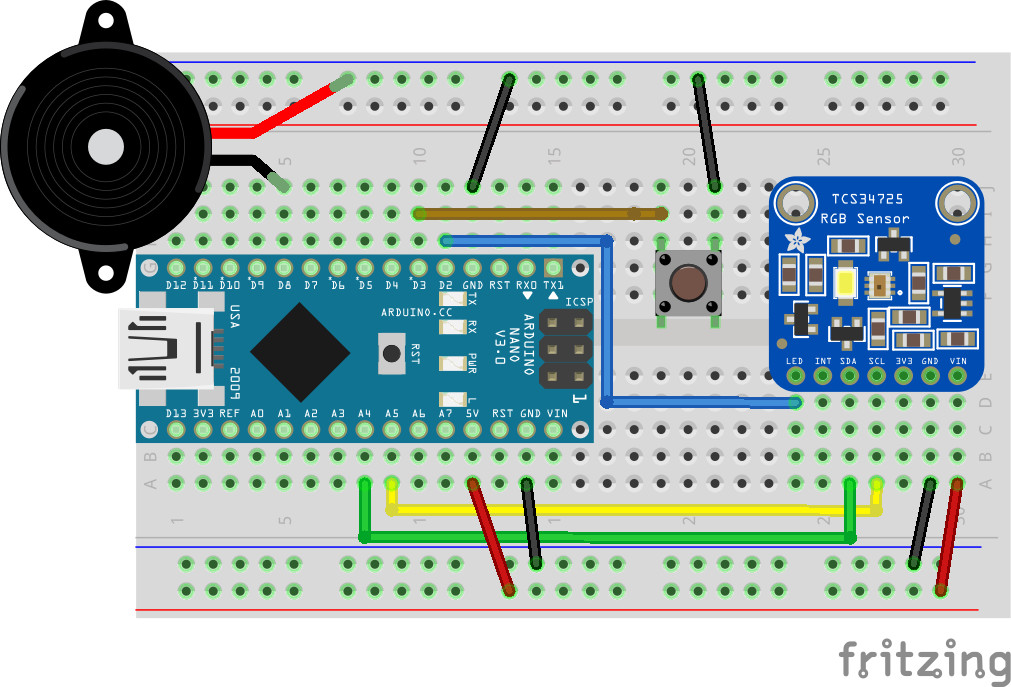
How can a seeing-impaired person select clothes with matching colors in the morning? Well, by converting the color information into a sound signal, which is the idea behind this project. The color is converted to the pitch of a sound and the brightness to its duration. Figure 1 shows the schematic of a prototype, with a piezo buzzer and an ams TCS34725 color sensor mounted on a small breakout board. Both are connected to an Arduino Nano.
This prototype system was developed as part of the course “From Sensor to Report” at Uppsala University, which teaches basic data-acquisition skills including interfacing of sensors and microcontrollers to the outside world. Therefore, we do not use ready-made libraries to interface the sensor, but code the basic functions to read out the sensors ourselves. Moreover, the logic to assign the sounds to the colors initially resides in a Python script on a laptop, rather than on the microcontroller. The PC and microcontroller are communicating via a serial interface. We developed a communication protocol to send sensor values from the Nano to the PC; commands are going in the other direction to activate the buzzer with the right frequency. Later, however, we extended the functionality to allow stand-alone operation on the Nano. Still, this is not a production-ready system, but a prototype that shows the basic functionality and invites the reader to experiment further.
Before starting to assemble components, we need to install the Arduino development system (IDE) in order to develop programs for the Nano. The IDE is available for all commonly used operating systems. Please follow the instructions relevant for your system. If you have not used Arduinos before, please follow this link to familiarize yourself with the Arduino IDE. As a second prerequisite, we need to install python, which is likewise available for all systems. Windows and MAC OS binaries can be found here and practically all Linux distributions have packages in their repositories. Again, follow the instructions for your system. But, enough of the preliminaries, let’s get started!
The Color Sensor
The heart of this project is the TCS34725 color sensor [6], which comprises a 3x4 photo-diode array (Figure 2).
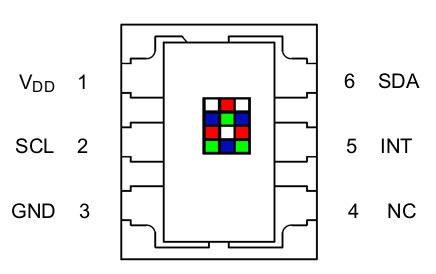
Color-sensitive filters mounted in front of the diodes make them sensitive to red, green, and blue light. Moreover, a clear diode without a filter provides information about the brightness. The analog signal from the diodes is converted to digital form by on-board analog-to-digital converters. The color information is made available via an I2C interface that connects to a microcontroller using only two wires for the communication, one for the clock signal (SCL) and one for data (SDA). The color sensor is then controlled by writing and reading registers on the device, but more on that later on where we describe the software.
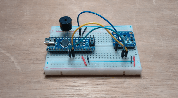
The hardware is assembled on a solder-less breadboard (Figure 3), pretty much following Figure 1 with the Nano shown on the left-hand side and the TCS34725 color sensor on the right.
The latter is connected by black and red wires to Ground and the 5 V rail at the bottom. Likewise, the corresponding pins of the Nano are connected to the power rails. The green and yellow wires connect the data (SDA) and clock (SCL) pins to the corresponding pins on the Nano, which are situated on A4 and A5, respectively. The blue wire that connects the digital output pin D2 to the pin labeled LED on the color sensor allows to control a white LED that is mounted on the breakout board. The buzzer is connected to pin D8 on the Nano. The button that connects pin D3 to ground with the brown wires triggers a conversion when operating the Nano in the standalone mode of operation, discussed below.
This circuit is brought to life by an Arduino sketch that first includes the wire.h library to provide low-level functions to communicate over the I2C lines. These functions are used right away in our own two functions I2Cread() and I2Cwrite(), which encapsulate all communication with the sensor.
I2Cread() is used to readout a sensor value or parameter, stored in so-called registers. As parameters, the function gets the address of the sensor on the I2C bus, here 0x29, and the register address (it took us a while to find out that 0x80 has always to be added to the latter). The function returns the contents of that register.
The function I2Cwrite() is used to send commands from the controller to the sensor, for example to set configuration values. This function gets the sensor and register addresses and, additionally, the new value that should be written to that register. No value (void) is returned from this function.
The Color Sensor-Based Application
Let’s return to our specific sketch. In the setup() function, we initialize the serial communication, the basic I2C functionality and the sensor (via function color_begin()). Inside the loop() function, which is executed indefinitely, we first check whether any command from the PC has arrived on the serial line. If that is the case, we read the register contents from the sensor, for all three colors. For one color, we have to read out two 8-bit registers and assemble the received bytes to a 16-bit word - following the instructions from the data sheet. This is shown in the following code snippet for the red color:
b3=I2Cread(TCS34725,0x16); // raw data, red
b4=I2Cread(TCS34725,0x17);
red=b4*256+b3;
Here b3 contains the least-significant byte and b4 the most-significant byte, which we multiply by 256 and add to b3 to obtain the 16-bit variable red. We treat the other colors likewise; only the register addresses are adapted.
Additionally, we use the brightness reported from the un-filtered diode and store it in the variable clea. This will determine the duration d of the sound. If the value of clea is less than 1000, we emit a 0.5 s long tone; and if it is larger, we use 1.5 s.
Now we read the received command and copy the result into a character array line, so we can use the standard C function strstr() to find out which command was sent. The following code snippet illustrates this:
Serial.readStringUntil('\n').toCharArray(line,30);
if (strstr(line,"color?")==line) {
Serial.print(clea); Serial.print(" ");
Serial.print(red); Serial.print(" ");
Serial.print(green); Serial.print(" ");
Serial.println(blue);
} else if (strstr(line,"tone_red")==line) {
tone(buzz, 262, d);
...
We see that the command color? causes the Nano to send the values of the four signals clea, red, green, and blue back across the Serial line. If tone_red is received, the built-in tone() command is used to activate the piezo buzzer - in that case with the frequency which is assigned to the red color. Several equally constructed strstr() blocks follow and trigger the appropriate actions.
Note that we use a simple protocol, based on sending character strings back and forth; a request from the laptop is terminated with a question mark, for example “color?”, and the Nano responds by sending the values back. An instruction is based on just sending the command, for example, “tone_red", which causes the buzzer to sound with 262 Hz for the duration specified by d. The communication vaguely mimics the SCPI command language that is supported by modern oscilloscopes and other test and measurement equipment. This makes interfacing to external programs that support accessing the serial line very simple; python, octave, Matlab, and Labview all support this.
The PC Program
We used Python 3 on the laptop to communicate with the Nano. The very basic code is shown in Listing 1.
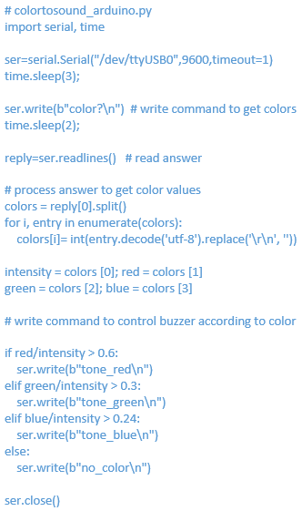
After importing support for the serial communication and basic timing functionality we open the Serial port to which the Nano is connected at the baud rate that matches that chosen on the Nano. Giving the operating system 3 seconds to establish the connection we then send the command “color?”.
Note that Python 3 encodes character strings as Unicode, whereas the Nano expects plain ASCII strings. We therefore have to prepend the letter “b” to the command “color?” in order to send the string as plain ASCII data. After another short wait, we receive the response from the Nano in the variable reply, which contains the values of the four colors that we individually retrieve with the .split() method and assign to mnemonic names, such as red.
Having the values available, we are ready to implement the logic to assign the sounds to the colors. This assignment is based on quite a bit of experimentation with colored paper sheets until a good setup was found. We used paper with a light, medium, and dark tone for each of the three base colors in order to calibrate the sensor. We repeatedly measured the respective color values at a fixed distance and used that information to specify the constants in the python code shown above. For example, the command tone_red is sent to the Nano, if the red component, normalized to the intensity, is larger than 0.6. Next we test the green intensity and send tone_green if the threshold is exceeded. Finally, the value of the blue component is tested. If even that does not qualify, “no_color” is sent to the Nano, causing it to emit the corresponding tone. Certainly some experimentation with the constants is needed in order to adapt the system to your wardrobe.
Standalone Version
The standalone version of the code is available in the Download section at the bottom of this article. It closely follows the example above, except that instead of waiting for a command arriving on the Serial line, the Nano now waits for the button to be pressed before reading the sensor and emitting the appropriate sound. Moreover, the color information is directly processed on the Nano as shown in the following snippet:
if (red/clea > 0.6) {
tone(buzz, 262, d);
} else if (green/clea > 0.3) {
...
If it is desirable to always illuminate the clothes with the built-in LED on the breakout board, we can turn it on with digitalWrite(led,HIGH) just before reading the registers from the TCS34725 and turning it off afterwards.
In a third stage, we can make the system portable by using a bare ATmega328, flashed with an Arduino bootloader, connected to the sensor. Powered from a battery as long as a button is pressed, the system starts up and continuously converts color to sound until the button is released to disconnect the battery. The software is also available from the article’s web page. Building the system is left as an exercise for enthusiastic readers.
In the “Sensor to Report” course the color sensor was quite popular. A second student, who wanted to monitor the color of the sky over a longer time to later analyze the data, used essentially the same setup with the Nano communicating with a host computer via the Serial line. She used a python script on a Raspberry Pi to store the data in a MySQL database, also running on the Pi, and later used Octave to prepare plots of the colors that were recorded over about a week. The plots were recorded just before Christmas and made us painfully aware of how short the days can get in Uppsala. Further data acquisition projects, following the same spirit, are described here.
About the Authors
 Volker Ziemann’s interest in electronics started with Elektor, around the time of the 40W Edwin amplifier (mid-1970s), but he got sidetracked to studying physics and worked with particle accelerators ever since — SLAC in the US, CERN in Geneva, and now in Uppsala, Sweden. Since electronics plays an important role for control and data acquisition in accelerators, his early interest has been useful throughout his career. He now teaches at Uppsala University and has authored three books, one of them about data acquisition with Arduino boards and the Raspberry Pi.
Annika Schlechter is studying toward an MSc in Physics at the University of Heidelberg, Germany. At the moment, she is continuing her studies during her Bachelor thesis at the German Cancer Research Institut in Heidelberg. This project began during an Erasmus semester at the University of Uppsala, Sweden, where she attended Volker’s lecture “Sensor to Report."
Discussion (3 comments)