
ESP32-RS-232 Adapter: A Wireless Link for Classic Test Equipment
on
Go wireless with RS-232! With an Espressif ESP32 module, you can give wings to a serial interface. In addition to its serial link communication capability, this handy adapter enables SCPI-equipped test equipment to receive commands and send data to the home network via MQTT.
As you work on different electronics projects over the years, the stack of test equipment on your workbench inevitably grows. In my case, I use a Keithley SourceMeter 2400 to identify faults in electronic assemblies, bring them into operation, or even measure the properties of various components. It’s also great for testing the leakage current of electrolytic capacitors or measuring their nominal capacitance. Another piece of equipment in my setup is an AOR AR5000 receiver, which I use to keep in touch with amateur radio contacts worldwide.
Both of these units, like many others in the lab, can be controlled by a PC thanks to their built-in RS-232 serial interface ports. The availability of USB-RS-232 adapter cables means that connection to a home PC should be fairly straightforward. In my case, the adapter worked fine with the AR5000, but communication with the Keithley SourceMeter was noticeably less stable. Characters occasionally get lost when sending SCPI commands, and connection dropouts are frequent.
The RS-232 Link
The RS-232 standard, defined back in the 1960s, is used to transmit serial data bits of a character using changes in voltage levels. The electrical properties were defined in V.28, with the overarching functionality regulated in V.24. The V.28 standard stipulates that, depending on the logical bit value, the sender signal voltage transition required to send a logic “0” should rise to a value from 5 to 12 V and fall to a value between -5 and -12 V to send a logic ”1.” The receiver has a slightly wider voltage window and will interpret a signal in the range from 3 to 12 V as a logic “0” and -3 to -12 V as a logic “1.” This takes into account signal degradation in the cable from noise, voltage drop, and signal edge rounding due to the cable impedance properties.
1In older, low-cost, USB-to-Serial adapters and some laptops, the signal level swing from the sender side barely gets greater than ±5 V or even ±3 V due to shortcuts made to the design of the RS-232 signal driver stage to minimize development and component costs. This has led to the popular belief that laptops and RS-232 devices often don’t work well together. The illustration in Figure 1 from a TI document illustrates the voltage levels that must be present to comply with the standard.
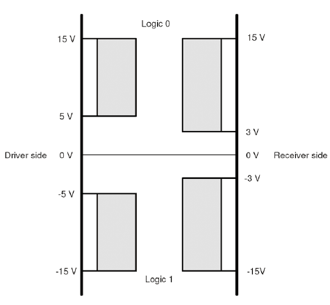
a receiver input. (Source: Texas Instruments)
Whether the aforementioned communication problem with the Keithley device was due to the use of a USB extension cable, a ground loop, or the electrical characteristics of the built-in transceiver is irrelevant at this point. After all, a USB cable stretched across the room is not only untidy but also a trip hazard. What’s needed is a neat, compact wireless solution!
I searched high and low for a ready-made solution to my problem, but all I could find were fairly large modules that mounted onto DIN rails or more limited DIY designs built to solve one specific problem. It was no good; if I wanted a neat, general-purpose RS-232 radio communication unit, I was going to have to sit down and design it myself.
The Design Criteria
This design is consciously aimed at the maker-lab environment and will not be a beautifully encased product you might find for sale in an electronics store. It is nevertheless good practice that the unit’s design is carefully considered so that it meets all the requirements for the job it’s tasked to perform.
An ESP32 does all the work
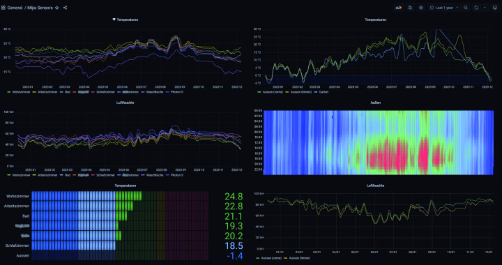
The RS2-32 gateway is primarily intended to transmit data to and from the network. This is typically done using TCP-Port 23 (Telnet). However, application-specific software adaptations should also be possible, which the user may decide on according to the application requirements. For me, an SCPI-to-MQTT service was important, so that the SourceMeter test equipment can transmit its readings overnight to Grafana (see below) for evaluation.
The ESP32 provides sufficient computing power beyond sending simple TCP packets so that the connected device can be easily integrated into Home Assistant or a comparable service via MQTT or to share it via a dedicated front end over the ESP32 web server.
An alternative would be the ESP8266, which takes up slightly less space and is a bit cheaper. However, the space saved comes at the cost of a significantly over-worked CPU and less RAM. On top of that, the ESP8266 lacks a Bluetooth module, which would be an ace up the sleeve in this application, alongside the desired Wi-Fi function.
The drawback of the ESP32 is, of course, its significantly higher power consumption, which peaks at around 500 mA from the 3.3 V rail. Of course, the CPU will not be continuously occupied calculating, but depending on how well-optimized the software is in the end, its peak current is likely to reach this magnitude, as indicated in Table 4.2 of the datasheet . A comparison with the ESP8266 datasheet shows that the ESP32’s power consumption is about 35% higher while transmitting and approximately 80% higher when receiving.
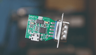
A neat, compact design
Most people would probably agree there’s already enough cable clutter snaking around lab benches and under desks. This circuit board can be soldered directly to a D-sub DE-9 connector and, in terms of size, works out to be not much larger than a standard IEC C13 (kettle lead) power connector including the bend radius of the power cable. This means the board, when plugged in, doesn’t increase the bench footprint of the RS-232 device. If a case is needed, it should be easy to 3D print; ideally, the circuit could even fit into a standard off-the-shelf enclosure.
Power from a Micro-USB connector
Power to the board is provided via a micro-USB socket as is already standard for many small devices. The +3.3 V required by the ESP32 is produced by the Advanced Monolithic Systems AMS1117 linear voltage regulator from the +5 V USB port supply. Although the AMS1117 is rated for up to 1 A, it gets quite hot on this relatively small board. A more efficient alternative would be the Texas Instruments TPS62291 step-down switch-mode converter, which comes in a 2 × 2 mm WSON-6 package. It also operates up to 1 A output and would save some space. Unless you have a microscope and all the necessary tools and experience for working down at this level, this chip is a bit more challenging to mount due to the tiny package outline. Those uncertain about soldering can find useful guidance and tips in the video.
It should also be noted that the supply of this particular component over the last couple of years has also been a little erratic. This has led to its price soaring to well over €20 from some distributors instead of the more usual €1.70. Comparing prices on the internet, you may be lucky enough to find units at prices reminiscent of the good old days. To reduce hassle, I just used the AMS1117 in this version, which makes hand soldering much simpler.
Power supply using the 9-way D-Sub
If you are not averse to occasionally going “off-piste,” the board could also be powered via the 9-pin D-Sub connector. With a slight adjustment to the terminal device or devices, the required 5 V can be provided via the RS-232 connector (and thereby avoid an additional power supply). The standard, however, does not support such a power supply option via the connector, so we have to be aware this will be a non-standard modification.
According to V.28, all signal lines can carry voltages from +15 V to -15 V, to supply power it makes sense to replace one of the pin functions which is seldom used. Pin 9 is designated as the Ring Indicator (RI) and is only used by a modem to signal an incoming call. RS-232 modems are now mostly redundant, which makes the RI pin a suitable candidate to use as a power supply pin.
First, however, we need to check what happens if we unexpectedly apply full voltage, for example, by connecting a terminal device that drives our supply line according to V.28. The +15 V would not be a problem for the AMS1117 itself; this voltage is within its specified limits. However, if -15 V were present, the internal protection diodes of the AMS regulator would conduct the usually 10 to.20 mA of RS-232 signal to ground. Empirical observations show that these diodes have no problem handling this, and according to their specification, the RS-232 drivers are short-circuit-proof, so no damage occurs here either.
The VDD supply voltage of our RS-232 transceiver is only specified up to 5.5 V and is also connected to the +5 V. Fortunately, in this case, the voltage drops to around 3.5 V due to current limiting by the RS-232 drivers. Admittedly, we are flying by the seat of our pants on this one, but we have only considered all these factors for the rare case that RI on Pin 9 will actually be driven by the terminal device. It is usually unconnected.
True RS-232
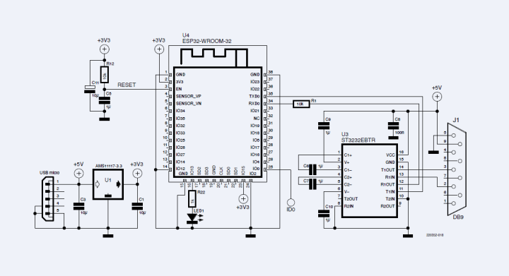
As mentioned earlier, our aim here is to adhere to the V.28 standard as closely as possible, which is why a data signal transceiver will be absolutely necessary. The ST232EBTR from ST will do the job and is available in a TSSOP-16 outline. This device is also quite affordable at around €1 and features an internal voltage doubler and inverter circuits, it generates supply voltages of plus and minus 10 V, which are used to drive the RS-232 signals, typically measuring around 9 V under normal operating conditions. The circuit diagram of the ESP32-RS-232 dongle with the ESP32-WROOM module (or the WROVER with PSRAM) and the two ICs: ST232EBTR and AMS1117, along with all peripheral components, can be seen in Figure 2.
Component Placement
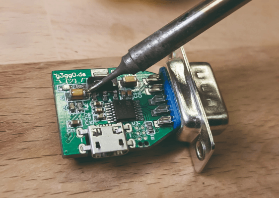
For such a small board with so few components, it makes little sense to have the components mounted professionally or to have the added expense of a layout stencil and subsequent assembly using a home hotplate. For this, PCB shown in Figure 3, we can get away using old-fashioned hand soldering methods because the component count is low, and the pads are accessible.
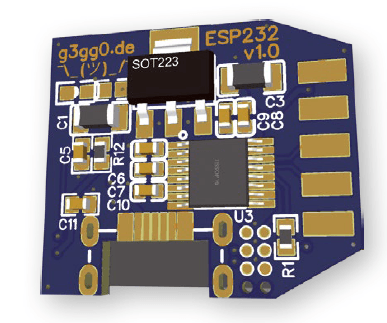
pads is ideal for hand soldering SMD chips
The first component to be assembled is the ST232 (U3). It is relatively flat, and the pins may require some rework to clean the joints. Next, the capacitors, resistors, and LED can be soldered in place followed by the AMS1117 (U1) and the USB socket. Now the ESP32 and, finally, the 9-pin D-Sub connector can be soldered.
Firmware
The firmware’s most basic function is to route characters received over the network to the RS232 port and vice versa, but thanks to the versatility of the ESP32, much more is possible here. The firmware, as found in the repository, currently offers two operating modes — Telnet and MQTT/SCPI — which are explained below.
Telnet / Raw TCP-Socket
As we already outlined in the design criteria, the primary function is to transfer data from the network to the RS-232 port. For such adapters, it’s common to transmit characters raw using the TCP-Port 23. This port was previously used for the Telnet connection to a server but is rarely used today (except in embedded systems). For our purpose of transmitting commands or measured values to and from serial devices, this is absolutely sufficient in a home network.
Telnet is a network communication protocol developed to enable the remote control of a computer over a network. It provides a text-based communication channel allowing a user to access a remote computer and execute commands there. This connection is bidirectional, so that both inputs and responses are relayed over the network. Originally developed in the more naive era of early internet standards, Telnet is often used in applications where simple, text-based communication is sufficient. It is, however, considered insecure as it lacks encryption, potentially allowing interception of all transferred data including passwords and other sensitive information.
For initial communication tests, you can use the telnet.exe tool, which came as standard in earlier versions of Windows. If this is not available, you can use the free and more universal alternative, PuTTY.
MQTT/SCPI
For applications which need to regularly capture measured values over periods of several hours, you can develop appropriate Python scripts or even start ready-made tools on your PC and read them via the Telnet port. A practical alternative to this, for those who already have established a suitable infrastructure in their domestic network, is to bypass the power-hungry PC altogether and provide a more simplified measurement setup.
Many households will already be running services such as MQTT, InfluxDB, and Grafana for capturing measurement values from sensors on a Raspberry Pi or via Docker Containers using their home NAS. Without going into too much detail and in simple terms:
- MQTT is a lightweight messaging protocol designed for efficient communications between devices in IoT and low bandwidth, high-latency networks. It uses an information broker with a publish/subscribe model to enable seamless data exchange with minimal overhead.
- InfluxDB is a time-series database, designed to efficiently handle high write/query loads for time-stamped data. Tags are key-value pairs for indexing while fields contain the actual data.
- Grafana takes data values from a database and displays the information in a user-friendly way, with user-defined graph axes.
For those with such a setup at home, this firmware provides the option to publish measurement values generated by the SCPI-speaking device directly to an MQTT broker for further dissemination.
The set of commands used by each SCPI device varies significantly. The only device currently supported by the code is the Keithley SourceMeter 2400. This, however, serves as a good starting point for anyone to add their own firmware variants. Skilled embedded developers are invited to expand the software functionality and share it with the community.
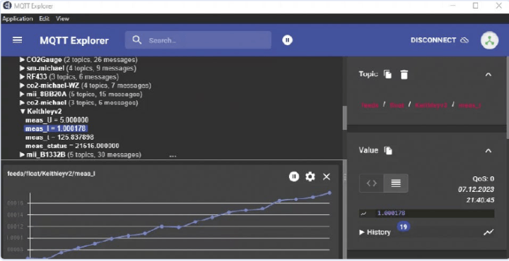
To see how measurement representations can look in different applications, refer to Figure 4 (Grafana), Figure 5 (MQTT Explorer, a comprehensive MQTT client for various platforms ), and Figure 6 (also Grafana). To make this possible, the ESP32 needs to take care of a few things, and for this it requires information that we need to provide via a web interface.
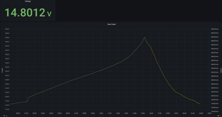
read by an ESP32-RS232 adapter
Wi-Fi Setup
If a configured access point (AP) is not found or none is configured, the ESP32 becomes active and offers itself as an AP with the name esp232-config. It’s best to connect to this AP using a Smartphone. After logging in, you can configure the most important parameters by accessing http://192.168.4.1/ via a browser. The web page hosted on the ESP32 can be seen in Figure 7.
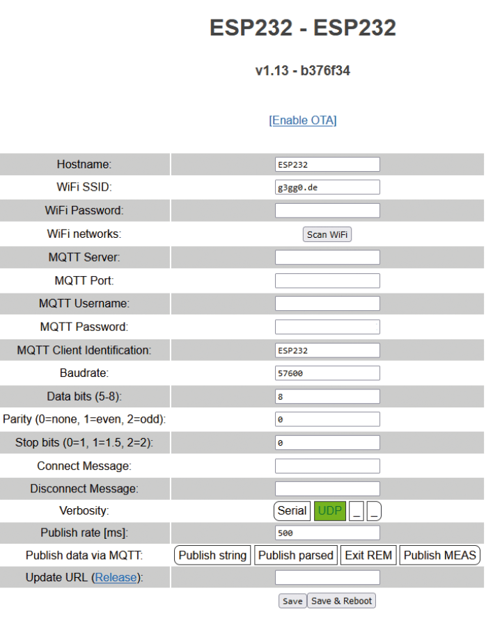
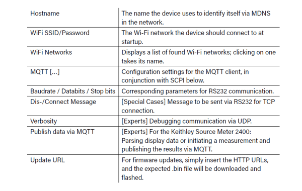
Table 1 explains what needs to be entered in each row.
OTA: Updates Over-The-Air
In the Arduino IDE or in PlatformIO, which I prefer, the ESP32 can be updated “remotely.” The underlying protocol is implemented by the ArduinoOTA component. While this feature facilitates frequent updates of the microcontroller, in practice significant drawbacks were revealed. It seems that constantly allocating and releasing buffers for each received UDP packet fragments the ESP32's memory led to unpredictable resets. To make matters worse, this happens regardless of whether OTA packets are in transit. You can imagine that a crash message output via the ESP32’s UART is rarely well-received by the connected device. Fortunately, there have been improvements that significantly reduce the crash rate. Due to this level of uncertainty, the OTA feature is only activated briefly and on user request, which is why there’s a field (Enable OTA) for it in the web interface.
Flashing
If you don't already have a Pogo-Adapter for the ESP32 modules, the microcontroller needs to be provided with the appropriate firmware after assembly using the transmit and receive data pins of the ESP32. To do this, download the source code from , import it into PlatformIO, compile, and finally, flash it to the board.
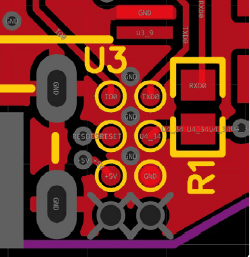
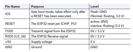
Provision has been made for a programming port at the bottom right-hand corner of the board. For occasional use, you can just link the IO0 signal to GND and solder the TXD0 and the RXD0 (Pin U4_34 on the microcontroller, see Figure 8) to a USB-UART adapter.
programmer.
As Table 2 shows, the ESP32 has a few “strapping pins” that need to be set when loading the ROM code using this method. In this setup, we only need to worry about one (IO0). Once the firmware is uploaded, an LED should start blinking after about 30 seconds.
The Ugly
The ESP32 has proven its capabilities in my projects. There were, however, initially various problems in the Arduino library regarding use of the UART buffer, leading to the code directly accessing the libraries in the IDF framework. Bugs in the ArduinoOTA library also led to me spending some nights burning the midnight oil in an effort to try and isolate the problems. As a consequence, there are certain workarounds in the source code. But since this firmware is open source, it will continue to evolve and benefit from improvements contributed by the community.
The Next Generation
What bothers me about v1.0 of the project until now is the somewhat cumbersome flashing process during the initial setup (or flashing to correct code errors). Thanks to a flash adapter with Pogo pins that I use for all my projects, the effort is reduced considerably, but not everyone has a suitable adapter on hand or likes working with jumper leads.
For this reason, the ESP32-RS-232-Adapter is moving on to its next incarnation and is currently being developed as version 2.0 using an ESP32-S3-PICO. There are already some initial prototypes produced, and they look promising. The PICO is a complete module with SPI flash and RAM, all integrated into an LGA-56 package. Although the PICO looks like a QFN outline at first glance, which is usually easy to hand solder, GND must be connected to an exposed pad, requiring the pad to be soldered through a hole during hand assembly. This package also has no lead frame, and the pins can only be soldered from the edge with difficulty. Ultimately, a (mini) hotplate would seem to be the best method to use here.
The significant advantage of the S3 is that it has a full USB peripheral, allowing it to be flashed or debugged. If necessary, ESP232 v2.0 can also be used as a USB-to-RS232 adapter.
Whether we’re just going around in circles and ending up where we started is a rhetorical question. When you think that the ESP8266 was from the start ideally capable for building a Wi-Fi-to-Serial bridge, it leaves you wondering why there still isn’t such a device available on the market today.
Editor's note: This article (220352-01) appears in Elektor March/April 2024.
About the Author
Georg Hofstetter’s interest in electronics was kindled in the era of the Commodore 64 and perfboard. After training as an electronics technician, he went on to complete a degree in computer science. Since then, he has been developing or reverse-engineering software and embedded systems, publishing selected projects on his website www.g3gg0.de. Some of the more well-known projects include firmware modifications for Canon DSLRs called Magic Lantern (www.magiclantern.fm) and for the Toniebox (https://gt-blog.de/toniebox-hacking-how-to-get-started).


Discussion (4 comments)