
Ideal Diode Controller: Diode Circuits with Low Power Dissipation
on
Reducing power dissipation from diodes is essential in all situations where high currents flow at relatively low voltages (e.g., when solar panels or lithium-ion batteries are connected in parallel). Ideal diode controllers have been developed to minimize power dissipation in such cases.
batteries are connected in parallel.
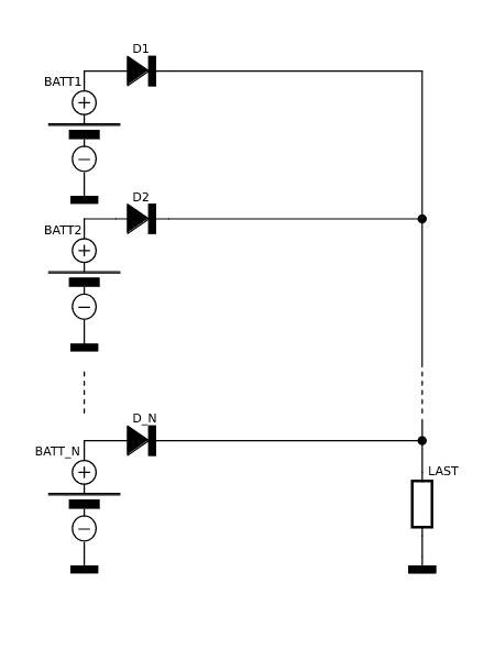
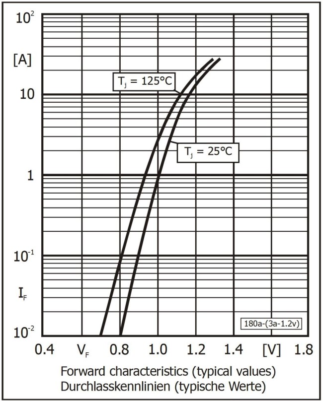
A typical diode use case is shown in Figure 1. There the diodes are required to prevent current from flowing from one battery or solar panel into another battery or solar panel. But if you consider the power dissipation of silicon diodes, for example a type 1N5404, the data sheet says that the forward voltage is 1 V at 3 A (Figure 2). This means the power dissipation at 3 A is a hefty 3 W.
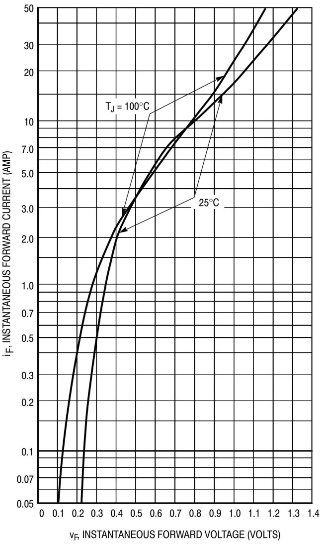
Things are a bit better if you use a Schottky diode such as the 1N5822, which can also handle 3 A. At this current level the voltage drop over the diode is only 0.45 V, corresponding to a power dissipation of 1.35 W as illustrated in Figure 3.
But if you want to use diodes at higher currents, such as 100 A or more (which is certainly realistic with lithium-ion batteries), the power dissipation rises to an unacceptable level of 50 W or more, even if you use Schottky diodes.
The Ideal Diode
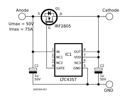
To reduce this power dissipation, Linear Technology has developed ideal diode controller devices such as the LTC4357. This controller has an input pin (anode), an output pin (cathode), and a ground pin. Combining the controller with an n-channel MOSFET, as shown in the circuit in Figure 4, produces an ‘ideal’ diode, and the LTC4357 has a rated maximum voltage of 80 V. Of course, the maximum rated drain-source voltage of the MOSFET must be at least equal to the voltage present between the input and output. The maximum diode current only depends on the maximum rated drain current of the MOSFET, and the power dissipation is solely dependent on the drain-source resistance of the MOSFET in the On state.
controller and a MOSFET.
In the typical application circuit shown in Figure 4, the LTC4357 basically operates as a comparator. When the input voltage is higher than the output voltage, Q1 is switched on, and otherwise Q1 is cut off to prevent current flow from the cathode (drain) to the anode (source).
Looking at Figure 4, you may wonder how the circuit can work with the LTC4357 supply voltage pin (VDD) connected to the output (cathode). The answer is that when the LTC4357 is powered up, it draws its supply voltage through the body diode of the MOSFET if no voltage from another source is present at the cathode. As an additional feature, the MOSFET is switched off if there is a short-circuit between the cathode terminal and ground.
In the illustrated application circuit, a type IRF2805 MOSFET is used. According to its data sheet, the drain-source resistance is only 4.7 mΩ. With a current of 3 A, the voltage drop over the MOSFET is therefore only 14.1 mV, so the power dissipation is a modest 42 mW. The following table shows comparative figures for the MOSFET and a diode (in this case an IXYS DSEI 120) at a current of 75 A.
| Component | Voltage drop | Power dissipation |
| IRF2805 | 350 mV | 26 W |
| DSEI 120 | 1.5 V | 112.5 W |
The Eagle files for the schematic diagram and layout of the previously illustrated application circuit are available at the Elektor Labs page for this project.
What About AC?
There’s a limitation with the LTC4357: it’s not suitable for rectification of AC voltages. To deal with this, Linear Technology also offers the LT4320, which can be used to build a bridge rectifier. The typical application circuit shown in Figure 5 is taken from the Linear Technologies data sheet.
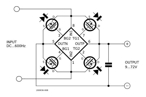
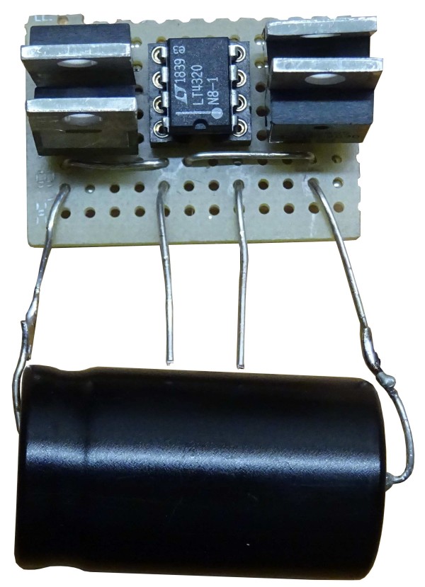
Bridge rectifiers for voltages from 9 to 70 V can be implemented in this way. The frequency range extends from DC to 60 Hz with the LT4320, or DC to 600 Hz with the LT4320-1. Here as well, the maximum current and power dissipation of the rectifier depend on the MOSFETs used. The Eagle files for the schematic diagram and layout (for SMD and THT versions) of this rectifiers circuit are also available at the Elektor Labs page for this project. The layout is designed so that the assembled circuit can replace conventional type BxxCyyyy bridge rectifiers. Figure 6 shows a rectifier circuit built on a piece of perfboard.
The Linear Technology ideal diode controllers allow the power dissipation of diodes and rectifiers to be drastically reduced. The increased circuit complexity (and additional cost) is entirely acceptable in circuits operating at high current levels.
Schematic diagrams for simulation with LTSpice are available for the LT4357 and LT4320 at the Elektor Labs page for this project. A video on this topic can be viewed on Youtube.
Questions or Comments?
Do you have any technical questions or comments about the ideal diode controller? Contact the Elektor editorial team at editor@elektor.com.
Discussion (1 comment)