
The Key Electronic Formulae Every Budding Engineer Needs
July 27, 2020
on
on
As soon as a resistor needs to be selected, it is time to pull out the correct formulae. It is also important to keep the various electrical laws that underpin our fascinating hobby or area of work in mind too. When trying to repair a device, or understand why a circuit doesn’t work, going back to fundamentals can provide a firm collection of facts upon which the next steps can be determined.
Perhaps of equal interest for some is the history of the people after whom these formulae and rules are named after. Long before the Internet and online ordering of components, the acquisition of electrical components for research would have been expensive. Furthermore, access to them would have been limited to those studying under some of these great scholars. It is amazing to think that, more than a century later, their hard work still plays a role in our lives on a daily basis.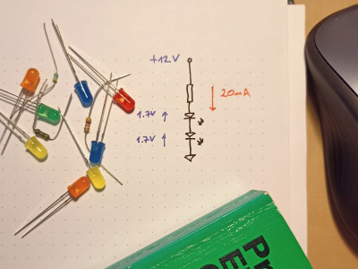 Much of early electrical engineering was focused on the challenges of the fledgling telegraph technology. Telegraphers used differing units for electrical resistance such as that defined by Moritz Herman von Jacobi or the German mile. These defined resistance in terms of lengths of wire of known cross-section. It was the British Association that managed to establish the ohm as the unit of measurement for resistance in the mid-19th century.
The unit was named after the German physicist Georg Ohm. His work in the early 19th century led to the formula V = I × R we use today, known as Ohm’s Law. The law can be rearranged in three different ways depending on whether the voltage (V), current (I), or resistance (R) needs to be calculated. These are:
A common first use for Ohm’s Law by students is to calculate the current limiting resistor for an LED. Given a 12 V power supply and two LEDs in series, the necessary resistance can be calculated. Firstly, the forward voltage of the LEDs is required. This could be around 1.7 V for a standard red LED. This is subtracted from the power source voltage:
From here, knowing that the LED’s operating current is, for example, 20 mA, the required resistor can be calculated:
With 20 mA flowing through our resistor, we can determine the power it needs to dissipate as follows:
This means we can safely select a ¼ W resistor for use in the application.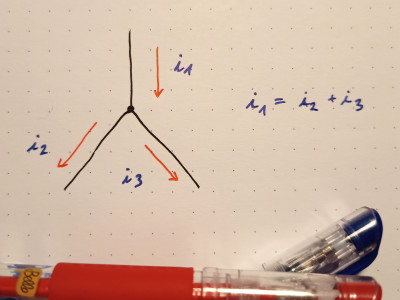 The equations discussed thus far seem simple enough and easy to use, but that is only because they are established and because we now work in standard units. At the time, standard units weren’t available and work such as Ohm’s was called “a web of naked fancies”. Such ‘new thinking’ was often incompatible with established theories.
Kirchhoff’s circuit laws, of which his Current Law is one, is another law that seems blindingly obvious today. It states that the algebraic sum of currents at any node in a circuit is zero. The reason two LEDs in series, as we analyzed above, only draw the same current as a single LED is due to this law. If we consider the connection point between the two LEDs as a node, the current entering the node from the first LED is 20 mA, as is the current leaving the node entering the second LED. Thus, the current flowing through the resistor must also be 20 mA.
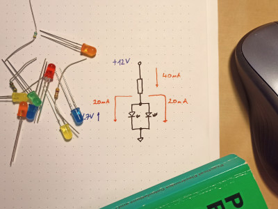 If we now modify our previous circuit by placing the LEDs in parallel*, we can examine the node where current flows from the resistor into the two LEDs. With each LED drawing a current of 20 mA each out of the node, it follows that the current flowing into the node via the resistor must be their sum, i.e. 40 mA. Assuming the same 1.7 V forward voltage, we can quickly calculate the required resistor value as follows:
With 40 mA flowing through this resistor, will we need a component with a higher power rating? This can be determined as before:
Such a circuit change may only be small and subtle, but it clearly shows a need to move to a ½ W resistor.
* Note: Operating LEDs in parallel like this is, in reality, not a trivial matter. For the purposes of demonstrating Kirchhoff's Law mathematically, it is fine, but in real circuits, there are some considerable challenges!
Perhaps of equal interest for some is the history of the people after whom these formulae and rules are named after. Long before the Internet and online ordering of components, the acquisition of electrical components for research would have been expensive. Furthermore, access to them would have been limited to those studying under some of these great scholars. It is amazing to think that, more than a century later, their hard work still plays a role in our lives on a daily basis.
Ohm’s Law
Much of early electrical engineering was focused on the challenges of the fledgling telegraph technology. Telegraphers used differing units for electrical resistance such as that defined by Moritz Herman von Jacobi or the German mile. These defined resistance in terms of lengths of wire of known cross-section. It was the British Association that managed to establish the ohm as the unit of measurement for resistance in the mid-19th century.The unit was named after the German physicist Georg Ohm. His work in the early 19th century led to the formula V = I × R we use today, known as Ohm’s Law. The law can be rearranged in three different ways depending on whether the voltage (V), current (I), or resistance (R) needs to be calculated. These are:
V = I × R, I = V ÷ R, and R = V ÷ I
A common first use for Ohm’s Law by students is to calculate the current limiting resistor for an LED. Given a 12 V power supply and two LEDs in series, the necessary resistance can be calculated. Firstly, the forward voltage of the LEDs is required. This could be around 1.7 V for a standard red LED. This is subtracted from the power source voltage:
12 V – 1.7 V – 1.7 V = 8.6 V
From here, knowing that the LED’s operating current is, for example, 20 mA, the required resistor can be calculated:
R = 8.6 V ÷ 0.02 A = 430 Ω
Electrical power
Of course, once the resistor value is defined we also need to make sure it is correctly dimensioned for the power passing through it. This leads us to another key formula. Power (P), measured in watts (W) is a measure of the rate (per unit time) at which electrical energy is transferred and can be calculated using the formula P = V × I. This can be combined with Ohm’s Law to allow the resistance to be used to calculate power as follows:P = V × I so P = V2 ÷ R or P = R × I2
With 20 mA flowing through our resistor, we can determine the power it needs to dissipate as follows:
P = I2 × R = 0.022 A × 430 Ω = 172 mW
This means we can safely select a ¼ W resistor for use in the application.
Kirchhoff’s Current Law (KCL)
The equations discussed thus far seem simple enough and easy to use, but that is only because they are established and because we now work in standard units. At the time, standard units weren’t available and work such as Ohm’s was called “a web of naked fancies”. Such ‘new thinking’ was often incompatible with established theories.Kirchhoff’s circuit laws, of which his Current Law is one, is another law that seems blindingly obvious today. It states that the algebraic sum of currents at any node in a circuit is zero. The reason two LEDs in series, as we analyzed above, only draw the same current as a single LED is due to this law. If we consider the connection point between the two LEDs as a node, the current entering the node from the first LED is 20 mA, as is the current leaving the node entering the second LED. Thus, the current flowing through the resistor must also be 20 mA.
If we now modify our previous circuit by placing the LEDs in parallel*, we can examine the node where current flows from the resistor into the two LEDs. With each LED drawing a current of 20 mA each out of the node, it follows that the current flowing into the node via the resistor must be their sum, i.e. 40 mA. Assuming the same 1.7 V forward voltage, we can quickly calculate the required resistor value as follows:12 V – 1.7 V = 10.3 V
R = V ÷ I = 10.3 V ÷ (0.02 A + 0.02 A) = 257.5 Ω
R = V ÷ I = 10.3 V ÷ (0.02 A + 0.02 A) = 257.5 Ω
With 40 mA flowing through this resistor, will we need a component with a higher power rating? This can be determined as before:
P = 0.042 A × 257.5 Ω = 412 mW
Such a circuit change may only be small and subtle, but it clearly shows a need to move to a ½ W resistor.
* Note: Operating LEDs in parallel like this is, in reality, not a trivial matter. For the purposes of demonstrating Kirchhoff's Law mathematically, it is fine, but in real circuits, there are some considerable challenges!
These formulae can help
If in doubt, get back to basics! The work undertaken by the physicists of the 19th century is as relevant today as it was back then. If your circuit isn’t working as expected, take a moment to compare reality with the theory as these formulae and laws can help clarify why the currents or voltages on your breadboard don’t align with your expectations.Read full article
Hide full article
Discussion (0 comments)