
Monitor and Debug Over the Air (OTA): A Solution for Arduino, ESP32 and Co.
on
IoT devices operating remotely ‘in the field’ benefit from the ability to perform software updates over the air (OTA). A good tutorial on the subject using the Arduino IDE can be found here (ESP32 Basic OTA Programming In Arduino IDE). However, this method has one drawback: the serial monitor is not supported, so that output and debugging information cannot be transferred.
On my last project, a garden watering system based on the ESP32, there was a problem with a malfunctioning sensor. Instead of laying a USB cable all the way across the terrace into the living room and to my computer, I started looking for a wireless solution. Despite an intensive search, I couldn’t find an off-the-shelf module that would do the job according to my requirements so I set about developing my own solution. I seemed to remember systems that enabled wireless transmission of serial interface data; in fact, I quickly found what I was looking for from a company in the Far East. The Wireless UART-RS232 long distance set offers transfer rates of up to 115,200 baud with configuration options and a range of up to 1 km. With a price of £50 for the sending and receiving pair, I thought this represented a good price/performance ratio for this project.
A USB-Host Adapter
The selection of a USB/serial converter turned out to be much more difficult. Although it would be possible to connect the serial data signal from the remote watering controller directly to the serial transmission system, I wanted a more universal solution using a USB port connection so that other types of development board could also easily use the link. For this you need to provide a so-called ‘USB host adapter’ which plugs into the USB port at the remote site and talks to the development board as a PC would. I struck lucky when I spotted the ‘USB-Host Shield’ for Arduino after some intense internet trawling at Sparkfun and here. The item was stocked by a local supplier so I put in an order and within a few days I was busy unwrapping it at my desk. It did not take too long for me to discover a problem. There are many different development platforms out there in the maker world and several different brands of USB interface chips. The ESP32 boards for example use the CP210x or FTDI chips, Arduino boards use the Atmel controller or FTDI chips. Unfortunately, the libraries for the Arduino USB Host Shield can only support one type of chip at a time. That means, you would need to make the host shield software configurable and find out which flavour of chip is fitted to the development platform you are using. Hardly a plug-and-play solution! Eventually, I found a USB-host interface board from the UK which was much more accommodating of different brands of interface chip (Figure 1).
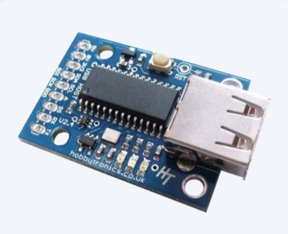
What is particularly interesting about this board is that it can work with a wide range of devices such as flash memory sticks, USB keyboards, USB joysticks, USB mice, PS3/PS4 dual shock controllers, and has serial drivers for FTDI, CP210X, PL2303, CH340/1 and CDC, MIDI devices and USB modems. A list of all the free firmware applications is given on their web site. If you know exactly the application you want to use the board for, you can specify it when ordering and it will be supplied with the firmware installed. For this application, I needed the USB Host - Serial Driver for FTDI, CP210X, PL2303, CH340/1 and CDC firmware; it supports all the relevant USB chips used by the different development boards.
For programming and configuring the wireless UART RS232 modules or the USB host board, at least one USB to serial converter is required, which can either be obtained from the same manufacturer of the wireless UART RS232 modules or, for example, from Logilink. For my project, I needed two RS232 level converters. I chose the good-old MAX232 solution.
Setting Up the Link
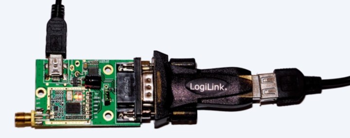
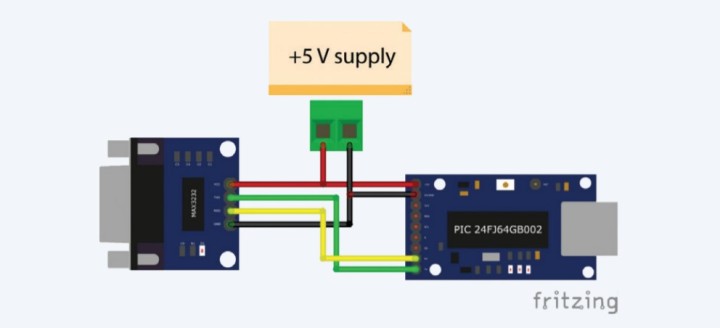
When I received the Wireless UART-RS232 Long Distance set, it was not clear to me how I should actually configure the modules. I contacted the seller and the next day received an email with the software, a manual and a link to a configuration video. First, I had to take the modules out of their plastic cases and solder a pin header to connector position J2 (a row of pads just in front of the RS232 connector). I then put jumpers on the pins according to the instructions so that the module enters the configuration mode. Next, I connected the module to the PC via the USB/serial adapter. The module is powered from a 5 V power supply (e.g., a USB plug-in power supply) via the mini USB connector (Figure 2).
If both LEDs light up, you can fire up the HY-TRP Setting GUI.exe program and set the correct COM port and the default baud rate to 9,600. Then click on the Open COM button and read out all values with Read All Settings. The values are set as shown in Figure 3.
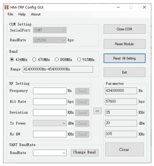
Further details can be found in the manual. Some issues of link reliability were resolved by reducing the transmission link baud rate down from 115,200 to 57,600. The USB host board has a buffer that tolerates different transfer speeds. Both of the modules must be configured identically. Lastly, when configuration is complete don’t forget to remove the jumpers.
USB Host-Board Configuration
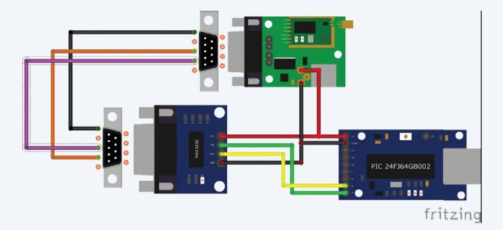
To program the USB host board with the correct firmware, please refer to the description. There are many programs available for download from Hobbytronics which can be flashed to the board. The correct firmware can be loaded onto the board using the instructions given here, and there you will also find a description of the parameters of the command interface. For configuration, the USB host board has to be connected to the MAX3232 level converter board as shown in Figure 4. The RS232-TTL converter connects to the RS232-to-USB adapter, which in turn connects to the PC via a USB cable. The circuit now only needs power from a stable 5 V supply.
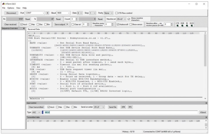
Now you can start a terminal program (here, for example, Hterm), select the correct USB port and set the baud rate to the default value of 9,600 baud. Clicking on the Connect button at the top left will connect you to the USB host board. At the top right Newline at and below the main window Send on Enter options are changed to CR + LF. If you now enter HELP in the input field of Input Control field below the main window, the current parameters should be listed as shown in Figure 5.
The parameters for our application are now modified using the input field of Input Control. First, we can enter BAUD 57600 command to change the baud rate which must match the baud rate set for the Wireless UART Systems. If you use Disconnect then Connect, to disconnect and reconnect the terminal to the system you should be able to check the communication link with the USB host board using HELP.
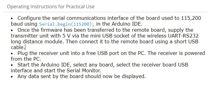
The USBBAUD 115200 command will set the USB baud rate to 115,200. This means that the serial interface of the connected Arduino/ESP32/ESP8266 board in the Arduino IDE must always start with the command Serial.begin (115200).
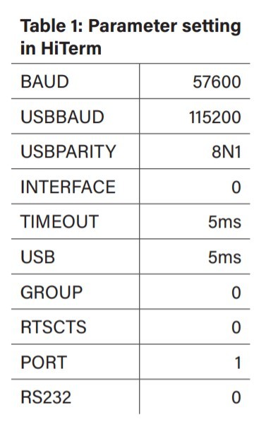
Default settings of USBPARITY, INTERFACE, TIMEOUT, USB, RTSCTS, PORT and RS232 are used. The default value of the serial data grouping option is OFF. The command GROUP 0 also sets these properties to their default value. Table 1 gives a summary of the correct settings. This completes the configuration.
Wiring the Modules
Before the transmitter (at the IoT board in the field) and receiver (at the PC end) can be wired up it will be necessary to remove the PCB mounted power supply barrel socket (next to the USB socket) on the Wireless UART-RS232 long distance Modules so that the pads are accessible.
On the transmitter side, the mini-USB socket of the USB host board will power the unit. Figure 6 shows the wiring at the transmitter end. To connect the Wireless UART-RS232 long distance module to the RS232/TTL adapter, you need to use a short cable terminated with male SUBD-9 connectors. Wires to Pin 2 and Pin 3 are switched over in the cable as shown in the picture.
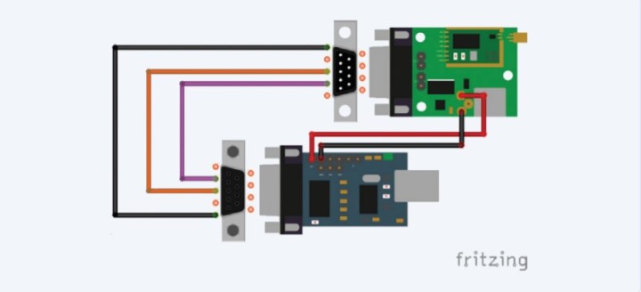
The compact module from is used as the RS232/USB converter for the receiver and is wired up according to Figure 7. I used a USB extension cable between the PC and receiver unit to give some flexibility in positioning the unit indoors.
Finally, I installed the transmitter and receiver unit into two matching enclosures. The tests of my OTA system showed consistent transmission through two floors with reinforced concrete ceilings. Altogether, the system provides a convenient and reliable long range ‘virtual USB cable’ facility useful when developing and debugging remote IoT applications.
Questions About OTA or Other Topics?
Do you have any questions or comments about this OTA application, OTA solutions in general, or any of the other topics this article? Email the author at peter.tschulik@chello.at or contact Elektor at editor@elektor.com. Subscribe to the OTA tag for notifications about future articles on the topic. This article will appear in Elektor (March/April 2022).
Discussion (1 comment)