Pin Maximization with Multiplexing and Charlieplexing
Ah, the age-old problem. You’ve got one oscilloscope, but five engineers want to use it; one telephone line, but three people want to make calls; 20 LEDs, but only eight GPIOs remain on your microcontroller. So, what do you do? You share! Or, in technical speak, you multiplex. Let's take a look at multiplexing.
Ah, the age-old problem. You’ve got one oscilloscope, but five engineers want to use it; one telephone line, but three people want to make calls; 20 LEDs, but only eight GPIOs remain on your microcontroller. So, what do you do? You share! Or, in technical speak, you multiplex. Let's take a look at multiplexing.
One of the biggest challenges when selecting a microcontroller (MCU) is finding a device with enough pins for the task that is within budget. Typically, a 64-pin device is more expensive than a 32-pin device. Around 10% to 15% of those pins will be power supply pins. What remains is a mixture of digital, analog, and special use case pins.
For example, there is a reset pin, pins for the crystal oscillator, and perhaps a dedicated pin to support a bootloader. And sometimes, pins are dedicated for use with specific peripherals, such as USB or I2C, because the circuitry around them is a little different.
So, let’s assume we’ve determined that our application requires 20 purely digital pins, perhaps for input switches and controlling LEDs for a human-machine interface. On a 32-pin MCU we subtract the power supply pins (e.g., 6), the analog-only pins (e.g., 8), USB and I2C (e.g., 4), and we’re left with just 14 pins. So, when putting your commercial hat on, can you justify selecting a higher pin-count, more expensive MCU where not all the pins are used? Or can some engineering cleverness turn 14 pins into 20 signals?
Subscribe
Tag alert: Subscribe to the tag Microcontrollers and you will receive an e-mail as soon as a new item about it is published on our website!
Multiplexing Started with the Telegraph
The idea of getting more out of a single electrical connection started with the telegraph. Once Morse and friends had worked out how to send bits of data over long distances by wire, it was clear that continuously adding wires to build capacity would be expensive. Not only that, it added more work for the team maintaining the network.
Naturally, a few clever minds of the day started pondering whether these single wires could be shared across multiple telegraphers so that two or more messages could be sent across each of the existing wires. One of these was Émile Baudot.
Émile Baudot invented a way to
multiplex several telegraph
operators over a single wire.
(Public Domain)
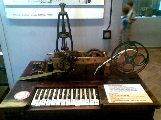
Baudot started working for the French Post & Telegraph Administration as an operator in the late 1860s. He was also exposed to the Hughes printing telegraph. Unlike traditional telegraph systems that used Morse’s dots and dashes that had to be transcribed back into readable text, the printing telegraph had an alphanumeric keyboard styled like piano keys. At the other end, the transmitted letters were transcribed to paper tape.
The system had to be synchronized at both ends. At the receiving end, a typewheel, much like a daisywheel printer head, rotated continuously. At the sending end, all the letter keys were sampled in the same order. If a key was pressed, the corresponding typewheel letter would be actuated as it passed over a paper tape. This limited the transmission of messages to around 40 words per minute (a word was averaged at five letters plus a space).
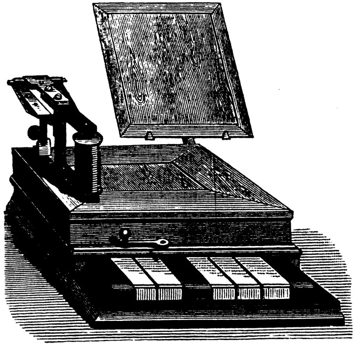
The Hughes printing telegraph avoided the need to learn Morse code. (Public Domain, Source: Olaf)
Baudot wondered whether this synchronization method could be used to share a single wire between more users. Digitizing the information, the letters to be sent, seemed like part of the solution. But Morse’s established code meant that the time to send each letter differed, ranging from a single short dot symbol to up to five long dashes.
This challenge was resolved by a new encoding scheme that consisted of the same number of equal-length symbols for each letter. Consisting of five bits, his system used positive and negative pulses to transmit each letter. By synchronizing both ends, up to six users could simultaneously send messages over a single wire. Well, that’s what it looked like. In reality, it was a time-division multiplexing system that provided each telegrapher a sixth of a slot to transmit their next letter.
The Baudot printing telegraph required the user to input 5-bit codes representing the letter or symbol to
be transmitted. Six of these units shared a single telegraph wire. (Public Domain)
Multiplexing for LEDs
Seven-segment LEDs and matrix keypads have been a mainstay of electronic systems for decades. Even before MCUs were commonplace, electronics engineers looked for ways to save on the number of signals required to implement these components.
Let’s take seven-segment LED displays as our first example. If you also include the decimal point, these devices contain eight LEDs. If you’re building a power supply, you’re probably looking at four digits total (XX.YY) to display the voltage or current. That leaves us needing 8 x 4 = 32 pins - that’s a lot.
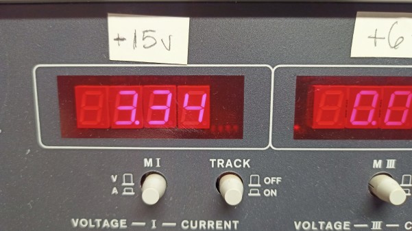
Four seven-segment displays on a bench power supply.
What is common to each segmented display are the eight connections and the common cathode. We also know that LEDs can leverage the visual persistence effect of the human eye. That means if we switch between the displays quickly enough (time-division multiplexing), the eye won’t notice that the LEDs have only been on for a fraction of a second. Something above 24 times per second would be appropriate.
Thus, if we connect the same segment LEDs of each number to the same MCU pin, we can save 24 pins. To determine which of our four seven-segment displays is driven, we need four pins to connect one of the common cathodes to ground. So now, to control 32 LEDs, we need 8 + 4 = 12 pins – 20 less than dedicating a pin per LED.
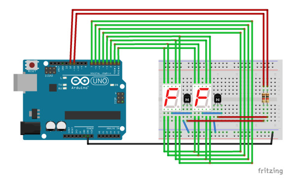
Two seven-segment displays share eight signals (segments plus decimal point). The UNO's
D11 and D12 pins engage one or the other displays, connecting the common cathode to ground.
If you want to control the display’s brightness, you can create a routine in a timer interrupt that controls the turn-on time of the common cathode pins.
Subscribe
Tag alert: Subscribe to the tag Arduino and you will receive an e-mail as soon as a new item about it is published on our website!
Multiplexing for Matrix Keyboards
The same approach can be used for a matrix of push-button switches as an embedded system input. If you have just two or three switches, you can probably combine them with a pull-up/down resistor and detect their status with the same number of GPIOs configured as inputs.
However, once you get above around six switches, it can make sense to implement a matrix to read them out. Rather than connect the switches to the power supply via pull-up resistors, the switches are connected to a GPIO output. When the output is high, and the switch is pressed, the input will detect it as a 1. You’ll need to retain the resistors to avoid shorting the Vcc to ground through the GPIOs.
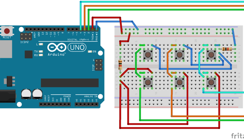
To make a matrix, strings of switches need to be engaged in rotation by some GPIO pins configured as outputs.
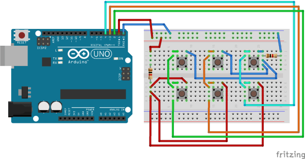
Starting with six switches, we group them into two groups of three. Each group of three has one side connected to a GPIO output. We then group them in twos, with the other side of each switch connected to a GPIO input.
Push button multiplexing: six buttons using five GPIOs.
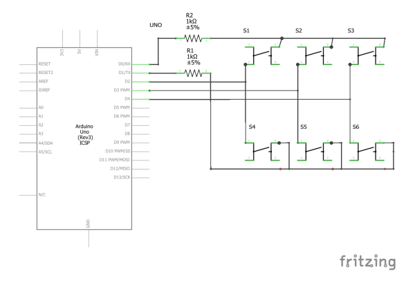
Schematic for the six-button multiplexed keypad.
In software, we enable the GPIO output of one column of push buttons, scan the three inputs, and then turn the output off again. The process is repeated with the second column. So, for six switches, we have used two outputs and three inputs – that’s five pins instead of six.
// PSEUDO CODE
// INITIALIZE PINS
SET D0 as OUTPUT
SET D1 as OUTPUT
SET D0 LOW
SET D1 LOW
// SCAN BUTTONS
SET D0 HIGH
READ D2, D3, D4 and STORE STATE as BUTTON 1, BUTTON 2, BUTTON 3
SET D0 LOW
SET D1 HIGH
READ D2, D3, D4 and STORE STATE as BUTTON 4, BUTTON 5, BUTTON 6
SET D1 LOW
It is important to scan through the columns fast enough to ensure that the input method remains responsive. Humans consider a response time of under 200 ms to be ‘instant,’ so you should scan your entire matrix of push buttons at least five times per second. This method is also suitable for detecting button press combinations, which can help provide more user interface functions than buttons.
Charlieplexing with LEDs
While multiplexing reduces the number of GPIOs needed to control LEDs, Charlieplexing enables you to use even fewer pins! This uses the fact that MCU GPIO pins have three states; high and low as an output and high impedance as an input.
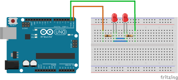
To start simply, we can connect two LEDs in opposing polarity between two MCU pins. When configured as outputs, if one pin is high and the other is low, one of the LEDs turns on. Reverse this, and the other turns on. To turn them off, simply set both GPIOs as inputs.
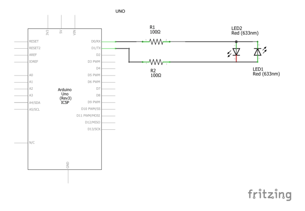
Principle of Charlieplexing with two GPIOs and two LEDs.
When an LED is switched on, the current passes through two current-limiting resistors. Thus, if you have calculated a 200 Ω resistor for your LEDs, you’ll need two 100 Ω current-limiting resistors.
Schematic for Charlieplexing two LEDs.
// PSEUDO CODE - CHARLIEPLEXING
// INITIALIZE PINS
SET D0 LOW
SET D1 LOW
SET D0 as INPUT
SET D1 as INPUT
// TURN ON LED 2
SET D0 as OUTPUT
SET D1 as OUTPUT
SET D1 HIGH
SET D0 LOW
// TURN ON LED 1
SET D1 LOW
SET D0 HIGH
// TURN LEDS OFF
SET D0 as INPUT
SET D1 as INPUT
SET D0 LOW
SET D1 LOW
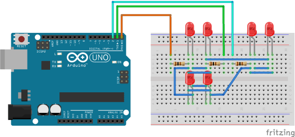
So far, so unimpressive. We’ve used two GPIOs to control two LEDs. The fun starts when we add an extra GPIO…and four more LEDs. We add two more opposing polarity LEDs between GPIO one and three and two between GPIO two and three. To control a single LED, one GPIO needs to be output high, one output low, and the third must be configured as an input.
Controlling six LEDs with three GPIO pins using Charlieplexing.
// PSEUDO CODE FOR CHARLIEPLEXING SIX LEDS
// INITIALIZE GPIOs
SET D0 LOW
SET D1 LOW
SET D2 LOW
SET D0 as INPUT
SET D1 as INPUT
SET D2 as INPUT
// TURN ON LED1
SET D0 HIGH
SET D1 LOW
SET D0 as OUTPUT
SET D1 as OUTPUT
// TURN ON LED4
SET D0 LOW
SET D1 LOW
SET D0 as INPUT
SET D2 HIGH
SET D1 LOW
SET D2 as OUTPUT
Table for control of six Charlieplexed LEDs
Output Pins
LED1
LED2
LED3
LED4
LED5
LED6
D0
OUT HIGH
OUT LOW
INPUT
INPUT
OUT HIGH
OUT LOW
D1
OUT LOW
OUT HIGH
OUT HIGH
OUT LOW
INPUT
INPUT
D2
INPUT
INPUT
OUT LOW
OUT HIGH
OUT LOW
OUT HIGH
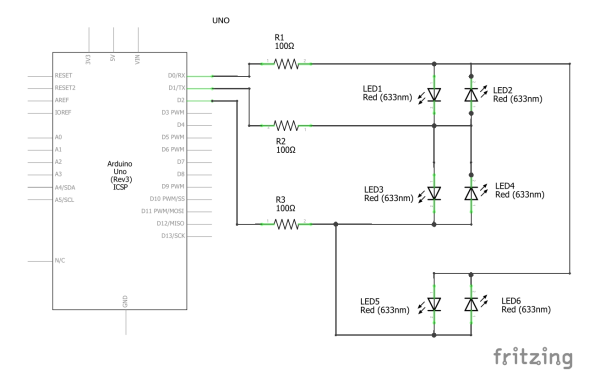
With two LEDs in series between pins 1 and 3 (Arduino D0 and D2 in the schematic below), you’d be correct to wonder why these LEDs don’t illuminate when attempting to turn on the single LED between these pins. This is a risk but relies on a low MCU supply voltage and the LEDs’ forward voltage. With a 3.3 V supply, the voltage across the two LEDs is 3.3 ÷ 2 = 1.65 V, not enough to illuminate and LED. Operating at 5.0 V may, therefore, cause issues.
Schematic for Charlieplexing six LEDs using an Arduino.
This leads to another consideration. The LEDs need to all have the same characteristic. LEDs of different colors often have different voltage drops, so there is a risk that, with mixed LEDs, an extra LED will turn on unwantedly under certain output conditions.
Like with multiplexing, Charlieplexing can also control the on-time of the high output pin to change the LED brightness. This requires a timer and its interrupt, along with some switch statements.
Since Charlieplexing opens up such great possibilities, a little equation will help to clarify how many LEDs can be controlled by how many pins.
LEDs = GPIOs × (GPIOs - 1)
So, for our four seven-segment displays (32 LEDs) from earlier, we would need seven GPIOs and would still be able to connect up to a further 10 LEDs for other uses.
So, Why Charlieplexing?
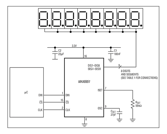
The term Charlieplexing comes from an engineer at Analog Devices, Charlie Allen, who championed the use of this technique within the organization. As a result, his name became a sort of shorthand when naming the control approach. Analog Devices actually manufactures some dedicated seven-segment LED drivers, such as the MAX6950.
This 16-pin chip can drive up to five seven-segment displays or 40 discrete LEDs. Just eight of the pins are used to control the LEDs. The control method used is slightly different from that described above, with a current source supplying the LEDs and MOSFETs providing the path to ground for the common cathode. The current source is adjustable from 2.5 mA to 37.5 mA, allowing LED brightness control. An MCU controls the device via SPI. If needed, several devices can be daisy-chained to control further segmented displays.
The MAX6950/1 uses a Charlieplexing approach to control up to 40 LEDs with just eight pins. (Source: Analog Devices)
Less Is More
The fun part of engineering is solving problems. Challenges, such as insufficient pins, occur regularly in embedded system designs. Creative use of the available resources, such as using a single pin for more than one function, is not new. This is why it helps to retain an open mind, remain inquisitive, and learn your discipline’s history. Just because it was invented over a century ago doesn’t mean it’s not relevant today!
Read full article
Hide full article
Add a rating to this article
★★★★★
★★★★★
Page 1 / 1
Login
No account yet?Register for free!
Forgot password?
Please enter your email address. Instructions for resetting the password will be emailed to you now.


Discussion (1 comment)