
SmartScope: Multi-Platform Measuring Instrument
In practice (cont.)
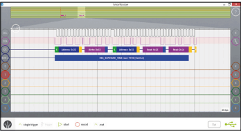
have been processed by a standard I²C decoder.
The results have then been converted
by a custom decoder into an easily readable format
The logic analyzer is just as easy to control as the scope section. Many electronic engineers rarely use these functions on a standalone device because the operation is so tricky. However, it’s a piece of cake in this case. You can set an 8-bit trigger word by clicking/touching the circles on the right of the display. Further development of this section is planned for the future as well.
The digital decoders in the SmartScope can be used on both analog signals as well as digital signals to decode various protocols. Some of the more popular ones have already been included. A small test with an I²C bus quickly revealed how useful these decoders are. Without too much effort, you’ll be able to see the values or addresses on the screen. It is even possible to set up two decoders in series, where the second one processes the results produced by the first decoder. An example of this is shown in thw figure, where the data in the hardware buffer has first been decoded by the standard I²C decoder. Its output is then processed further by the second decoder, which displays the results in an easily readable format: It shows the register number followed by the value of the next two bytes, combined as a word.
Read full article
Hide full article
Discussion (1 comment)