Embedded software typically remains unchanged after the product it powers is launched. So how can you be sure that your code is bug-free? Here we delve into the world of software testing to find out!
Embedded software typically remains unchanged after the product it powers is launched. So how can you be sure as you can be that your code is bug-free? Here we delve into the world of software testing to find out!
In “The Art of Software Testing” by Glenford J. Myers, the author starts by asking the reader to consider how to test an example program. If you’ve never written a software test before, you suddenly realize how difficult testing is. Where to start? What to cover? When to finish? But perhaps the most crucial question is: what is software testing?
Myers provides us with an excellent definition to answer this last question:
“Testing is the process of executing a program with the intent of finding the errors.”
Software often gets a bad name. Unlike hardware, such as a circuit board or chip design that stays fixed over the product’s lifetime, the software can be changed. So, the thinking goes, you don’t need to be so strict with its development as any errors can be fixed with relative ease. While this holds true for an Internet-connected machine in an office or data center, it doesn’t if you’re building satellites with a 20-year mission life.
Embedded software development doesn’t fit into this “we can fix it later” mentality because the software is inextricably linked to the hardware, especially code that is close to the peripherals. Additionally, most microcontrollers aren’t connected to the Internet and, if they are, such as an IoT sensor, the available bandwidth probably isn’t enough to support uploading a new firmware image.
There is also another challenge. If you are developing code on a PC, you can run tests relatively quickly and see the results on your screen. On a microcontroller, you probably don’t have a screen. Or a keyboard, for that matter. So how do developers test embedded software?
Testing Embedded Software Against Requirements
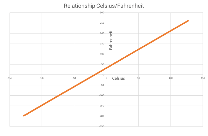
The first step towards successfully testing embedded software is a good definition of what the software should do. A requirements document should be written that explains the expected functionality and any limitations. For example, if you have a function that converts temperature measurements from Celsius to Fahrenheit, one requirement would be that the conversion is accurate across all values. The mathematical conversion, to recall, is:
TempF = TempC × (9/5) + 32
However, developing code for embedded systems often demands that we operate under the constraints of the limited resources of small microcontrollers. So, without floating-point support, that might mean developing a function using only integer math. This inevitably causes higher levels of error in the result than you’d expect from a floating-point implementation. So this would be declared in the requirements, probably as the level of accuracy that can be expected.
Integer maths may also limit the range of values that can be converted. A signed eight-bit char restricts the input range from -128 to +127, but also restricts the result to the same range. This implicitly restricts the input range from -88°C to +52°C which converts to -127°F to +127°F. While this all sounds very limiting, it is quite a realistic restriction for an eight-bit microcontroller targeting temperature measurements in the home. A comparison of code using eight-bit char and float implementations is provided at the end of this article.
Relationship between Celsius and Fahrenheit from -128°C to 127°C
It is also essential to consider tests that you know should fail. For example, a conversion of -100°C should not return -148°F for our optimized function implementation. If it does, there may be something wrong. Things like this can occur when char is not restricted to eight bits on some processor architectures.
These limits in functionality and input/output range will also help us define our tests.
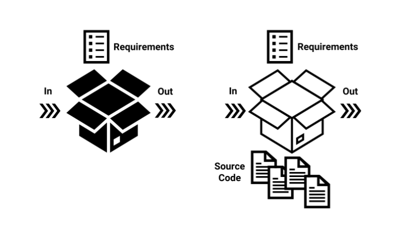
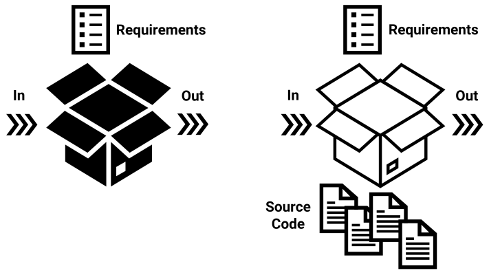
Black Versus White-Box Testing
With the specification in hand, there are two fundamental approaches to developing the tests: black and white-box testing. Black box assumes you test the code according to the specification without knowing the implementation. White box testing considers the specifications during test development but with an understanding of how the code works.
In the case of our temperature conversion function, black-box testing could result in an exhaustive collection of tests. All possible valid inputs could be tested as defined in the specification (-88 to +52°C). The result, in Fahrenheit, would be checked according to the accuracy specified (+/- 1°F). In this example, the number of tests that result is large but manageable. However, if we were to support 16-bit values, or have multiple input values, the number of test cases that result quickly become unmanageable, both from the perspective of quantity and text execution time.
Black box testing develops testing based on the requirements alone. White
box testing additionally uses an understanding of the code's implementation.
Black-Box Testing
To make testing more manageable, some assumptions about the code being tested can be made to reduce the number of tests. For example, if the function converts 25°C correctly, it probably works correctly for 26 and 24 too. This is known as an equivalence class and is used to formally reduce the number of test cases without detriment to testing quality.
There are other strategies for reducing the number of test cases. Boundary-value analysis examines the boundary conditions of equivalence classes. In our example case, we’d look at the limits of the input values as defined by the specification (e.g., -88 to -86°C, and +50 to +52°C). As a programmer, we also know that issues can occur when variables are incorrectly defined, such as unsigned char instead of char. Therefore, tests for inputs of -1°C, 0°C, and 1°C are sensible, as are tests expecting results of -1°F, 0°F, and 1°F.
The full range of black-box testing approaches, as listed by Myers, are:
Equivalence partitioning.
Boundary-value analysis.
Cause-effect graphing: a formal method for test development suited to complex systems.
Error guessing: an informal method of test development driven by intuition and experience.
White-Box Testing
White-box testing takes a different approach. The test developer knows the implementation of the code. In our example, the function only contains one line of C source code: the mathematical equation to convert Celsius to Fahrenheit. Thus, the tests that would result wouldn’t be much different from those created using a black box approach.
However, should the source code contain decisions, such as if and switch statements, things change. With knowledge of the logic of the program, a tester can create tests that ensure all possible paths through the code are exercised. Thus, the test cases will pass some seemingly odd value combinations, so that code lines deep in the software are reached. Again different approaches allow teams to achieve varying depths of test coverage.
Myers lists the following:
Statement coverage: Ensure all statements are executed.
Decision coverage: Ensure all decision statements are tested to deliver true and false at least once.
Condition coverage: Ensure conditions of decision statements are tested to deliver true and false (such as if(A && B) ).
Decision/condition coverage: Both approaches are needed in code with a more complex flow to exercise more possible paths.
Multiple-decision coverage: Typically known as modified condition/decision coverage (MC/DC), this thorough approach also covers paths that the above alternatives can hide. It’s used in testing safety-critical software deployed in some automotive, medical, aerospace, and space applications.
Examples for equivalence classes and boundary value analysis for our temperature conversion function.
As you research software testing, you may also come across gray-box testing. This lies between the two approaches described above when the test developer has some insight into the code’s implementation, but less than is available for white-box testing.
When to Test Embedded Software
It is never too early to start testing. And while it is tempting to write tests for your own code, it should be the task of someone unfamiliar with the software. The above test approaches result in many tests that can take hours to execute. However, you’ll want to check if your test environment is working before starting an overnight test run. Therefore, it is worthwhile developing a test case with a handful of tests that can prove this. This is known as a smoke test.
The naming of tests relates roughly to the stage of development of your project. Tests for our temperature conversion function are termed unit tests. These test a function or module in isolation. Such code could be tested on a PC as it is universal and does not depend on any capabilities of the target microcontroller. Software to support unit testing includes Unity, designed with embedded developers in mind, and CppUnit for C++.
Tests are typically created using an assertion, a statement of the expected correct result. If the result is incorrect, the test failure is noted and reported upon completion of all the tests. An example using Unity is provided below:
// Example tests developed using Unity
// Variable value test
int a = 1;
TEST_ASSERT( a == 1 ); //this one will pass
TEST_ASSERT( a == 2 ); //this one will fail
// Example output for failed test:
TestMyModule.c:15:test_One:FAIL
// Function test; function is expected to return five
TEST_ASSERT_EQUAL_INT( 5, FunctionUnderTest() );
Testing protocol stacks is more challenging, as these expect to share data with layers above and below. To achieve this, software implementations known as a stub simulate the expected behavior.
Code that operates directly on the peripherals of a microcontroller is more challenging to test. One approach is to develop a hardware-in-the-loop (HIL) setup. For example, when testing code that initializes the UART, a second microcontroller could be used to confirm the correct operation for each test. Alternatively, a logic analyzer with a programming interface could capture the output, checking the baud rate, and correct parity and stop bit configuration.
Later in the development process, the various software modules will be combined. For example, we may wish to output our Fahrenheit result using a circular buffer linked to the UART interface. This stage requires integration testing to determine if the individual software modules still operate correctly when linked with one another. For embedded systems, this will also require a HIL approach.
For a completed product, system testing is needed. At this stage, there is little need to examine the code’s functionality. Instead, the test team is focused on overall functionality. This will examine if a button press results in the correct response, the display outputs the correct messages, and the resultant functionality is as expected.
Embedded Software Testing - Not as Easy as It Sounds
Testing is a complex matter, with challenges ranging from which tests to implement to how to execute the tests. Luckily, plenty of good resources are available that explain formal testing approaches. Even Myers’ book, written in the 1970s, has relevance today. Test development is also eased thanks to a range of open-source testing frameworks, reducing the barrier to entry for embedded developers wanting to improve their testing approach.
Example Code for Converting Celsius to Fahrenheit
Eight-bit microcontrollers operate more efficiently with eight-bit values. Furthermore, they are unlikely to include any hardware to accelerate floating-point math. Thus, it makes sense to write processor-optimized functions where possible that are fast and efficient. By limiting the range of Celsius values supported, the following char-based temperature conversion function is five times faster that the same function using float variables. The execution times are based on an Arduino MEGA (ATMEGA2560) compiled with the standard Arduino IDE settings.
// 8-bit Celsius to Fahrenheit conversion function.
// Required 5.5µs to execute
// Limited to Celsius range of -88°C to +52°C
char convertCtoF(char celsius) {
int fahrenheit = 0;


Discussion (0 comments)