
extremely accurate digital wall clock [110167-I]
The extreme accuracy! Definitely it is a feature of Maxim DS3231, a extremely accurate I2C real time clock (RTC) with integrated temperature compensated crystal oscillator (TCXO) and crystal.
The extreme accuracy! Definitely it is a feature of Maxim DS3231, a extremely accurate I2C real time clock (RTC) with integrated temperature compensated crystal oscillator (TCXO) and crystal.
The integration of the crystal resonator enhances the long-term accuracy of the device, the maximum error in a year is less than 64 second, over a temperature range 0 to 40ºC. The device incorporates a battery input which maintains running of the device in the absence of main power.
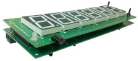
A PIC16F873A micro controller is used to interface the RTC and to drive seven segment LED displays. The micro controller has an I2C port which makes easy interfacing to the RTC. The design is simple 24/12 hour clock which incorporating six seven segment LED's and two input switches. The individual segments of each displays are connected together. The displays are numbered from left to right, the 2nd and 4th displays are flipped upside down to align decimal points in the displays to makes clock colon between hours – minutes and minutes – seconds. The PCB design takes care for this and tied together all segments at same position in the display.
The power supply for the micro controller is regulated with a 5V linear regulator and the displays are connected to a higher (9V) unregulated supply. This makes the design to capable of driving bigger displays which has large voltage drop per segment – such as 6.8V - due to more number of LED's in series. The common anode of each display is drive with help of two general purpose transistors, which not only to meet high current requirement but also to isolate micro controller output pins form high voltages. The PORTB pins are activate LED segments with help of a switching transistor.
Real Time Clock (RTC) DS3231
The DS3231 is a serial RTC driven by a temperature compensated 32kHz crystal oscillator (TCXO), and provides a stable and accurate reference clock. The temperature sensor, oscillator, and control logic form the TCXO. The controller reads the output of the on-chip temperature sensor and uses a lookup table to determine the capacitance required, adds the aging correction in AGE register (Not used in this project - use of the aging register is not needed to achieve the given accuracy) and then sets the capacitance selection registers. With the clock source, the RTC provides seconds, minutes, hours, day, date, month, and year information, and can be accessed via I2C bus. The device monitors the level of VCC to detect power failures and to automatically switch to the backup supply when necessary.
On first power up the micro controller initialize the RTC to generate a 1Hz square wave at the INT/SQW pin by writing 0x00 to the control register of RTC. This is connected to the external interrupt (INT) of the micro controller hence to set INTF flag in the micro controller at each high to low transition at RB0/INT. This is used to initiate a reading time registers of the RTC. A 1Hz colon also generates from polling the status of RB0/INT. The displays are multiplexed at a frequency of 1kHz.
DISPLAY
One of the attraction of this design is it big (2.4”) and brighter seven segment LED displays, so the clock can be read easily from a reasonable distances. The displays are multiplexed but provided sufficient average currents for high brightness. The display brightness can be adjusted as a user setting, which is stored in the eeprom, so the user can be change it any time. A bi-color LED is used to show AM (green), PM (red) if the clock operates in 12 hour format.
OPERATION
Only two push buttons are in this circuit to make adjustments. Press down SW1 for 1 second bring the circuit into time adjusting mode. Now the digits starts to blink, it means these digits are going to change. The blinking digits can be selected by a short press of SW1, from seconds, through minutes – hours – 24/12 hour selection - to exit. Pressing SW2 increments the selected digits to its upper limits then turn around, except for the “seconds” digits, these will be changed to zero, and if the seconds are greater than 30, it will increment minutes digits by one. Pressing SW2 when the device not in time adjustment, shows the temperature in ºC with sign. The temperature sensor has an accuracy of ± 3 ºC and with a resolution of 0.1 ºC.
COCLUSION
The circuit provided here is a basic wall clock with big displays, and features such as alarm, remote control for adjusting time and alarm, synchronization between PC via infrared connections are possible. The circuit, pcb design, and the source code written in C are attached with this document. A 9V, 500 mA unregulated power supply is sufficient for the circuit operation with an good brightness, and a CR2030 lithium battery is used as a backup supply for the RTC.
Want to build a project?
Bring your design to life with the Elektor PCB Service, powered by Eurocircuits. Upload the project files and order professionally manufactured PCBs or assembled boards through a proven European production platform.
Supporting KiCad, Eagle, Gerber, and ODB++ formats, the service is suitable for everything from prototypes and validation builds to series production and volume manufacturing.
Made in Europe. Fast. Reliable. Professional.
Discussion (1 comment)