
RF Power Meter with 1MHz-10GHz bandwidth and 55dB dynamic range (160193)
What is it: An RF Power Meter is a device which you can use to measure the power a transmitter outputs. Why did I built it? Read all about it!
What is it
An RF Power Meter is a device which you can use to measure the power a transmitter outputs. See also the Elektor Labs version.
Why did I built it
I'm a member of the model aircraft club FMS Spaarnwoude near Amsterdam and I started building and flying drones. I currently own an octocopter with 1 m span and added a camera with gimbal and a live video link to it. But here in the Netherlands the regulations are strict. On the 5.8 GHz band the maximum transmission power is 25 mW. Which is more than enough because you are also not allowed to fly higher than 100 m and your aircraft always has to be in visible range. But because I am flying near the biggest civil airport in the Netherlands, Schiphol Airport, I want to be sure that I am not transmitting more power then allowed. A friend of mine bought an RF power meter from ImmersionRC, but it costs around €190, which I find way too expensive. I told him that I probably could make my own RF Power Meter for about €50. It turned out to be even less.
How does it work
It was actually not that hard to design a RF Power Meter. There are integrated circuits called Log Detectors which translate measured power into a voltage. So it was just a matter of searching the right log detector. I ended up using the AD8317 of Analog Devices. It has a 1 MHz to 10 GHz bandwidth and a 55 dB dynamic range. I used the basic schematics as drawn in the datasheet and also used the PCB layout suggested by the datasheet for my own design.
The only disadvantage of using the AD8317 is that it comes in a CP-8-1 SMD package. Which is quite an unusual package I believe. It is only 3x2 mm and has seven pads underneath the package. Six of them just barely visible and one middle pad which cannot be reached. The middle pad is attached to GND and used as a thermal pad. It is hard to solder this kind of package with an solder iron because only 0.1 mm of the outer pads are exposed on the outside and you need to use a magnifying glass. With a solder iron it will also be difficult to solder the thermal pad because it cannot be reached at all. But I just finished building my own reflow oven out of a €30 toaster and a Zallus controller (which is really good), so I thought it would not be any problem to mount the package on the PCB. It is wasn't a problem at all. And it can also be done using a rework station with hot air gun. No problem at all. Just be sure not to use too much solder paste.
Schematics
The input comes in at X2, the maximum input is about 0 dBm, so you will have to use an attenuator when the power is more than 1 mW. The absolute maximum is 12 dBm, but all above that will not give a good reading. R1 and R2 form a 52.3 Ω resistance and combined with the internal input impedance of the AD8317 it will give a broadband input impedance of 50 Ω. C1 and C2 are DC blocking capacitors and together with the input impedance they will create a high pass filter with its corner at around 68 kHz. R3 is used for temperature compensation and I chose it to be 500 Ω because it is the recommended value when measuring 5.8 GHz, which I will probably use the most. See the datasheet at page 12 for other values. C3 is there to define the low pass demodulation filter of the output signal Vout. I took the default value of 8p2 because I'm not interested in demodulation. The output signal of the AD8317 is directly connected to the analog input A0 of an Arduino Nano. I chose the Arduino Nano because it is cheap ($4), easy to program and fast enough for our purposes. U1 is an LM4040 2.048 V external voltage reference. The internal reference of the Arduino is not accurate enough. An 2x16 LCD in 4-bit mode is used to display the measured values. Three buttons with pull-down resistors R7, R8, R9 are added to be able to navigate through the menus. R5 is used for adjusting the LCD contrast. R6 is in series with the LCD backlight to limit the current. The PCB does not contain a voltage regulator. The regulator of the Arduino Nano is used to power the other components as well.
PCB Design
I designed the double layer PCB in Eagle. The RF part is layed out as advised by the datasheet. I want to shield the RF part so I made a gap in the silkscreen for that purpuse. But it also works fine without the extra shielding. The rest of the board is quite straight forward. It is possible to make the board smaller by placing the arduino and RF components underneath the LCD. But I like the size as it is now. It is also easier to connect the mini USB to the Arduino when programming it. I've let Seeed Studio make the PCB, it only costs only $14 for 5 PCBs (which is the minimum amount you can order) and I am very pleased with the quality.
Software
The software is quite simple. The main loop of the software first takes 500 samples then it calculates the average power, peak envelope power, minimum power of the last 10 s, maximum power of the last 10 s and the modulation index. It then draws the screen and then it starts taking the next set of 500 samples.
Before reading the calculated values from the display the proper attenuation and frequency must be selected. The selected frequency must be near the frequency of the signal being measured. The selected frequency can be 900 MHz, 1.8 GHz, 2.2 GHz, 3.6 GHz, 5.8 GHz or 8 GHz. The conversion of the measured voltage by the ADC and the actual power in dBm is a linear function with a slope of -22 mV/dB, but the starting point of the function is different for each frequency. The starting points of these frequencies are in the datasheet. It is possible to add other frequencies, but you will have to calibrate them with a power source of which you know the power it outputs for that particular frequency. Since I do not have such a device I am not able to calibrate the device, I took the values from the datasheet. Therefore I did not add a calibration function to the software yet.
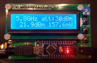
The software will also give you a warning when too much power is put into the device and when the amount of power is too low. Too low power will result in a large error according to the datasheet. By pressing the up or down button you can scroll through the measure menus. All power values are in dBm and Watt. You can select the frequency and attenuation by clicking the enter button when in the main screen. Pressing the enter button when in the min or max screens will reset the 10 s history which is used to calculate the min/max power and modulation index.
Attenuators
I started with a cheap 30 dB attenuator from Aliexpress, but I know these are not very accurate. So I do not know the exact attenuation. I also do not know the frequency charcteristics. So I ordered a VAT-20W2+ (20 dB) and VAT-30W2+ (30 dB) attenuator from Mini-Circuits. These come with a datasheet and I added those models with their characteristics to the software. Now it is possible to either select one of those models of set a custom attenuation. When selecting a model, the software will set the attenuation for the selected frequency according to the datasheet provided by the manufacturer of the attenuators.
Case
I've designed a case in DesignSpark Mechanical which can be printed with a 3D printer. These and the stl files have been added to this article.
Bill of materials
Part Value Package Costs (euro)
C1 47nF C0805 0.08
C2 47nF C0805 0.08
C3 8p2F C0603 0.08
C4 100nF C0805 0.08
C5 100pF C0805 0.08
J1 6-20V SPC4078 1.21
PCB1 ARDUINO_NANO 4.00
R1 51Ω R0603 0.02
R2 1.3Ω R0603 0.02
R3 500Ω R0805 0.02
R4 620Ω R0805 0.02
R5 10kΩ LI10 0.02
R6 330Ω R0805 0.02
R7 10kΩ R0805 0.02
R8 10kΩ R0805 0.02
R9 10kΩ R0805 0.02
S1 DOWN B3F-10XX 0.60
S2 ENTER B3F-10XX 0.60
S3 UP B3F-10XX 0.60
U$1 AD8317ACPZ-R7 11.59
U1 LM4040C20IDBZTG4 SOT95 3.19
U2 LCD-16X2 5V 3.95
X2 SMA-142-0701-801/806 8.00
PCB 2.00
30dB attenuator 8.00
Total costs 42.52
UPDATE
Software V1.1
- Added the ability to select a predefined attenuator profile of the Mini-Circuits VAT-20W2+, VAT-30W2+ or a custom attenuation. When selecting one of the two profiles, the correct attenuation is selected for the selected frequency.
- Attenuations now have 0.1 dBm accuracy.
- Attenuation settings now have been moved to a separate menu item.
Schematics / board
- Added a diode for polarity protection
If you have any questions please ask. I'm happy to answer them. You can use and change the software as you like. Maybe you can post a better version on this page or send it to me or add some more features. I was not able to test the modulation value becaus I currently do not have a signal generator which can generate AM signals. Maybe someone else can test it and send me the results. The function may be useless.
Regards,
Joost Breed
Joost Breed
Want to build a project?
Bring your design to life with the Elektor PCB Service, powered by Eurocircuits. Upload the project files and order professionally manufactured PCBs or assembled boards through a proven European production platform.
Supporting KiCad, Eagle, Gerber, and ODB++ formats, the service is suitable for everything from prototypes and validation builds to series production and volume manufacturing.
Made in Europe. Fast. Reliable. Professional.
Updates from the author