Article
RF Power Meter
For measurements up to 10 GHz

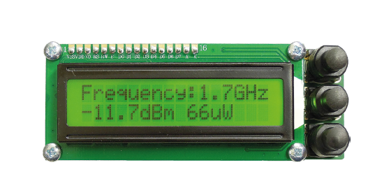
Radio remote controls for model aircraft and similar devices are rightly subject to strict regulations. They govern not only the transmit frequency, but also (and primarily) the transmitter power output. With the RF power meter described here, you can easily check how much power you are transmitting, at frequencies up to 10 GHz.
Gerber file
CAM/CAD data for the PCB referred to in this article is available as a Gerber file. Elektor GREEN and GOLD members can exclusively download these files for free as part of their membership. Gerber files allow a PCB to be produced on an appropriate device available locally, or through an online PCB manufacturing service.
Elektor recommends the Elektor PCB Service service from its business partner Eurocircuits or Eurocircuits as the best services for its own prototypes and volume production.
The use of our Gerber files is provided under a modified Creative Commons license. Creative Commons offers authors, scientists, educators and other creatives the freedom to handle their copyright in a more free way without losing their ownership.
PCB
Extra info / Update
Please note that while the original article from 2018 mentioned that parts or complete kits could be purchased in our Store, this is unfortunately no longer the case. We don't have them in stock anymore. We are sorry for the inconvenience.
Component list
Component List
PCB # 160193-1 (RF module)
Resistors
R1 = 52.3Ohm, 1%, 100mW (ERJ2RKF52R3X, Panasonic)
R2 = 499Ohm, 1%, 62.5mW
R3 = 200Ohm, 1%, 62.5mW
R4 = not mounted
R5 = 0Ohm, 1%, 62.5mW
R6 = 1kOhm, 1%, 62.5mW
Capacitors
Default: SMD 0402
C1,C2 = 47nF, 10%, 25V, X7R
C3 = 8.2pF, ±0.5pF, 50V, C0G/NP0
C4 = 100nF, 10%, 16V, X7R, SMD 0603
C5 = 100pF, 10%, 16V, C0G/NP0
Semiconductors
IC1 = AD8317ACPZ-R7, SMD LFCSP_VD (CP-8-1)
Miscellaneous
K1 = SMA, 50Ohm, straight, edge mount (142-0701-801, Johnson/Cinch)
K2 = 5-pin (1×5) pinheader, vertical, 0.1" pitch, through-hole
K3,K4 = 2-pin (1×2) pinheader, vertical, 0.1" pitch, through-hole
PCB 160193-1 v1.0
Component List
PCB # 160193-2 (main board)
Resistors
R1,R2,R3,R5 = 10kOhm, 5%, 0.1W
R4 = 1kOhm, 5%, 0.1W
R6 = 330Ohm, 5%, 0.1W
P1 = 10kOhm, 20%, 0.25W, SMD (Bourns 3314G-2-103E)
Capacitors
Default: SMD 0805
C1,C3 = 100nF, 50V, 10%, X7R
C2 = 2.2µF, 25V, 10%, X7R
Semiconductors
D1 = 1N4007, 1000V, 1A, THM
IC1 = MCP1501-20E-/SN, SMD SOIC-8
Miscellaneous
K1 = DC power connector, 3A, 1.95mm, Lumberg NEB 21 R
S1,S2,S3 = pushbutton, PCB SPST NO, Multimec RA3FTH9
S1,S2,S3 = round cap for pushbutton, black, height 16mm, Multimec 1S09-16.0
LCD1 = LCD module 2×16, 80×36mm, 3mm mounting holes
LCD1 = 1×16 header, vertical, 0.1" pitch, through-hole
MOD1 = 160193-1, RF-module
MOD2 = Arduino Nano
PCB 160193-2 v1.0
Optional (not recommended)
For LCD: 1×16 bus strip, vertical, 0.1" pitch
4 standoffs, M3, 12mm, F/F
4 screws, M3 (length > 6mm)
For MOD1: 2 1×2 and 1 1×5 bus strips, vertical, 0.1" pitch
For MOD2: 2 1×15 bus strips, vertical, 0.1" pitch
Depending on how the RF power meter is fitted in an enclosure, additional M3 standoffs (M/F), M3 screws and nuts may be necessary.


Discussion (8 comments)