Contactless Thermometer
Are you running an infrared temperature?
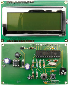
This thermometer measures at the same time both the ambient temperature and the temperature of any object placed within its ‘field of view’. And even though the ambient temperature range ‘only’ goes from ?40 to +125 °C, the object temperature can be from ?70 to +380 °C, and all with an accuracy of 0.5 °C and a measurement resolution of 0.02 °C.
Materials
Gerber file
CAM/CAD data for the PCB referred to in this article is available as a Gerber file. Elektor GREEN and GOLD members can exclusively download these files for free as part of their membership. Gerber files allow a PCB to be produced on an appropriate device available locally, or through an online PCB manufacturing service.
Elektor recommends the Elektor PCB Service service from its business partner Eurocircuits or AISLER as the best services for its own prototypes and volume production.
TIP: your first PCB at AISLER is free up to €30 with using the coupon code ELCCBB at checkout.
The use of our Gerber files is provided under a modified Creative Commons license. Creative Commons offers authors, scientists, educators and other creatives the freedom to handle their copyright in a more free way without losing their ownership.
Extra info / Update
* PIC16F876A microcontroller
* Four line × 20 character LCD display
* Displays ambient and object temperatures
* Stores minimum and maximum temperatures
* Runs off two 1.5 V cells
* Open-source software
Components
The BOM (Bill of Materials) is the technically exhaustive listing of parts and other hardware items used to produce the working and tested prototype of any Elektor Labs project. The BOM file contains deeper information than the Component List published for the same project in Elektor Magazine. If required the BOM gets updated directly by our lab engineers. As a reader, you can download the list here.
Want to learn more about our BOM list? Read the BOM list article for extra information.
Component list
R1,R4,R6 = 10kOhm
R2, R5 = 100Ohm
R3 = 1.5kOhm
P1 = 10 kOhm trimpot, horizontal
Capacitors
C1,C3 = 100µF 16V, radial, lead pitch 2.5mm
C2 = 470nF 63V, MKT, lead pitch 5 or 7.5mm
C4 = 10µF 25V, radial, lead pitch 2.5mm
C5, C8 = 22pF ceramic, lead pitch 0.2’’ (5.08mm)
C6 = 100nF ceramic, lead pitch 5 or 7.5mm
C7 = 10nF ceramic, lead pitch 5 or 7.5mm
Inductors
L1 = 10µH, Panasonic type ELC08D100E (RS Components)
Semiconductors
IC1 = LT1300
IC2 = PIC16F876A-10E/SP, programmed, Elektor # 100707-41
D1 = 1N5817 (must-have Schottky)
D2 = 3.3V 0.4W zener diode
Miscelllaneous
Sensor type MLX90614ESF-BAA or MLX90614ESF-AAA (see text)
LCD1 = LCD, 4 lines of 20 characters, e.g. Displaytech 204A
X1 = 20MHz quartz crystal, HC18/U case
S1 = pushbutton, 1 make contact, ITT type D6 if fitted on PCB
S2 = swich, changeover, or wire link
DIL IC sockets: 1 pc 8-way; 1 pc 28-way
Pinheder pins, lead pitch 0.1’’ (2.54mm)
Pinheder sockets, lead pitch 0.1’’ (2.54mm)
PCB, Elektor # 100707-1
Discussion (0 comments)