
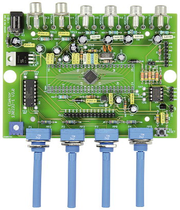
ADAU1701 Universal Audio DSP Board
drag ‘n drop DSP’ing—and no SMDs to solder
Continue reading this article with an Elektor Membership.
Join tens of thousands of engineers and electronics enthusiasts worldwide as a
member. Enjoy access to Elektor Magazine, the Elektor library, exclusive discounts,
early notification about Academy Pro products, and more. Select a membership
today and start exploring everything Elektor has to offer. Log in here if you are already a member.

PRINT (Gold)
- 8x Elektor Magazine (Print)
- 8x Elektor Magazine (Digital)
- Access to the Elektor Archive*
- Access to over 5,000 Gerber files
- 10% at the Elektor Store*
plus a delivery charge of 20 euros (US, UK, Ireland).
*Member discount and unlimited archive access only for full GOLD or GREEN members. Trial members have limited access to the online archive.
DIGITAL (Green)
- 8x Elektor Magazine (Print)
- 8x Elektor Magazine (Digital)
- Access to the Elektor Archive*
- Access to over 5,000 Gerber files
- 10% at the Elektor Store*
* Member discount and unlimited archive access only for full GOLD or GREEN members. Trial members have limited access to the online archive.

BUY THIS ARTICLE (PDF)
Gerber file
CAM/CAD data for the PCB referred to in this article is available as a Gerber file. Elektor Green and Gold members can exclusively download these files for free as part of their membership. Gerber files allow a PCB to be produced on an appropriate device available locally, or through an online PCB manufacturing service.
The use of our Gerber files is provided under a modified Creative Commons license. Creative Commons offers authors, scientists, educators and other creatives the freedom to handle their copyright in a more free way without losing their ownership.
Components
The BOM (Bill of Materials) is the technically exhaustive listing of parts and other hardware items used to produce the working and tested prototype of any Elektor Labs project. The BOM file contains deeper information than the Component List published for the same project in Elektor Magazine. If required the BOM gets updated directly by our lab engineers. As a reader, you can download the list here.
Want to learn more about our BOM list? Read the BOM list article for extra information.
Want to build a project?
Bring your design to life with the Elektor PCB Service, powered by Eurocircuits. Upload the project files and order professionally manufactured PCBs or assembled boards through a proven European production platform.
Supporting KiCad, Eagle, Gerber, and ODB++ formats, the service is suitable for everything from prototypes and validation builds to series production and volume manufacturing.
Made in Europe. Fast. Reliable. Professional.
Bill of Materials
Resistors
(all fixed Rs 5%, .25W)
R1,R18 = 100Ohm
R15 = 330Ohm
R4,R10,R11,R12,R13 = 470Ohm
R21,R22,R23,R24 = 560Ohm
R2 = 1kOhm
R3,R5,R14 = 2.2kOhm
R25,R26 = 10kOhm
R16,R19,R20 = 18kOhm
R17 = 47kOhm
R6,R7,R8,R9 = 1MOhm
P1,P2,P3,P4 = 10kOhm potentiometer, linear law
P5 = 470Ohm preset (trimmer)
Capacitors
C1,C2 = 22pF
C4 = 3.3nF
C24,C26,C28,C30 = 5.6nF
C6 = 56nF
C3,C8,C9,C10,C11,C12,C14,C15,C21,C22,C32,C34,C36 = 100nF
C5,C7,C13,C16,C33,C35 = 10µF 16V, radial, 2.5mm pitch
C23,C31 = 47µF 25V, radial, 2.5mm pitch
C17,C18,C19,C20 = 100µF 16V, 2.5mm
Semiconductors
D1,D2,D3 = 1N5817
D4,D5,D6,D7 = BZX79-C3V3 3.3V zener diode
IC1 = 24LC256-I/P, DIL8 case
IC2 = MCP604-I/P, MCP6004, DIL14 case
IC3 = ADAU1701JSTZ (LQFP48 case)
IC4 = TS2940CZ-3.3
LED1 = LED, 3mm
T1 = BC327
T2 = DO NOT FIT
Miscellaneous
K3,K4,K5,K6,K7,K8 = RCA/cinch socket, PCB mount
K1 = DC power adaptor connector
S1 = pushbutton w. tactile feedback
X1 = 12.288MHz quartz crystal
JP1 = 2-pin pinheader, 0.1’’ pitch
K10 = 4-way pin header, 0.1’’ pitch
K9 = 5-way pin header, 0.1’’ pitch
K11 = 14-way pin header, 0.1’’ pitch
K12 = 7-way pin header, 0.1’’ pitch
Jumper
PCB, Elektor Store # 130232-1, comes with ADAU1701JSTZ presoldered
Semi-kit, Elektor Store # 130232-71, includes PCB 130232-1 and all through-hole parts
Enclosure = Multicomp MCRM2015M (Farnell 1520399)
We buy at:

Discussion (5 comments)