Want to repurpose an operational amplifier from a previous project or an old parts collection? You can construct a specialized op-amp tester quickly and inexpensively.
Want to repurpose an operational amplifier from a previous project or an old parts collection? Be careful: its functionality might be compromised. Testing an op-amp with a multimeter for a simple pass/fail result isn't as straightforward as it is for components like resistors, coils, fuses, diodes, or capacitors. You can construct a specialized tester for op-amps quickly and inexpensively.
Op-Amp Tester Circuit
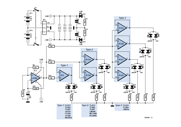
Refer to the test circuit, which consists of a simple squarewave oscillator (IC1) that oscillates with a frequency of approximately 1 Hz. As the designer, Dirk Schumacher, explains, the output of the oscillator (on pin 6) swings between “high”, +(Vb–0.5 V), and “low”, –(Vb–0.5 V), with a period of about 1 s.
Figure 1: The circuit can test single, dual and quad op-amps.
“The results of the test are displayed using low current LEDs. If the output of the op-amp is high, the red LED will light; if the output is low, the yellow LED will light. The op-amps under test will need to be able to sink and source a current of at least 2 mA,” Schumacher explains. “The test unit is powered from two 9 V PP3 (6F22) type batteries (BT1 and BT2). D15 and D16 indicate when the supply voltage is present on all the relevant pins of the oscillator and of all the test sockets.”
Quick go/no-go testing for operational amplifiers.
The design should be a handy addition to your electronics workbench.
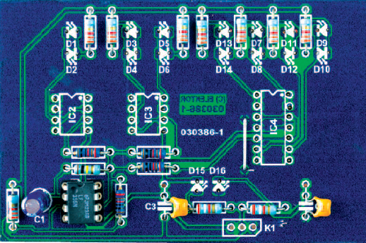
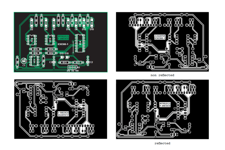
The PCB
More About the Tester
The article “Opamp Tester” appeared in Elektor 3/2005. Elektor Members have full access to Elektor’s library, which includes this informative article.
Subscribe
Tag alert: Subscribe to the tag Circuits & Circuit Design and you will receive an e-mail as soon as a new item about it is published on our website!
Read full article
Hide full article
Add a rating to this article
★★★★★
★★★★★
Page 1 / 1
Login
No account yet?Register for free!
Forgot password?
Please enter your email address. Instructions for resetting the password will be emailed to you now.


Discussion (0 comments)