Design Rewind: DIY Waterflow Monitor, Acoustic Sensor, and More
Elektor has a long history of excellence in electronic system design. Let's look at some interesting projects from past August editions: a waterflow monitor, an audio T-board, and much more.
It’s time to take another look back at past editions of Elektor Mag. This time, we focus on articles published in past August editions of your favorite electronics magazine. After reviewing these designs and articles, head over to Elektor Labs to post your projects.
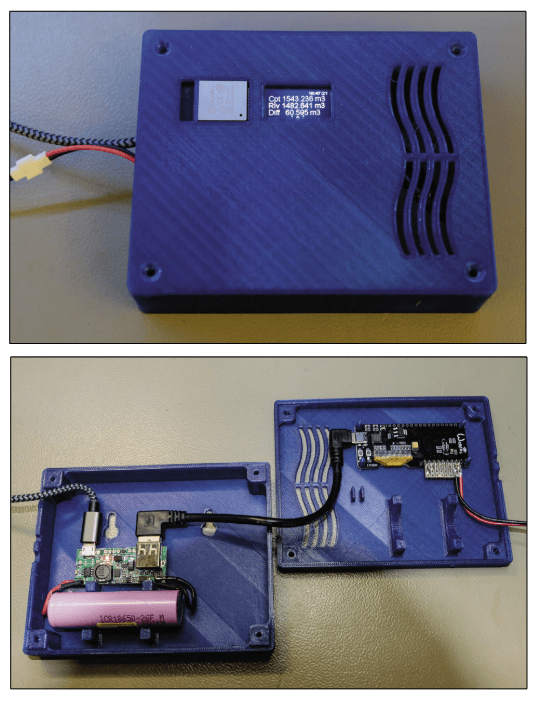
Waterflow Monitor with ESP32 (July/Aug 2019)
Many of the articles featured in Elektor Mag feature smart DIY solutions to common challenges and problems. Denis Lafourcade's ESP32-based waterflow monitor project is a great example. He designed the system as a handy tool for measuring his water consumption. It does the following: senses and processes metered impluses, displays hourly/daily/total consumption, detects suspected leaks, transmits alerts via text, and more.
The the complete waterflow monitor.
"The system starts up after power is applied, looks for the programmed WiFi network, sets the time and waits for a user connection while monitoring the pulses from the meter," he explained. "It should then be accessed from the web page using the address on the third page of the screen, to set the actual value of the meter, that of the last reading and the consumption alert threshold."
Subscribe
Tag alert: Subscribe to the tag Home Automation and you will receive an e-mail as soon as a new item about it is published on our website!
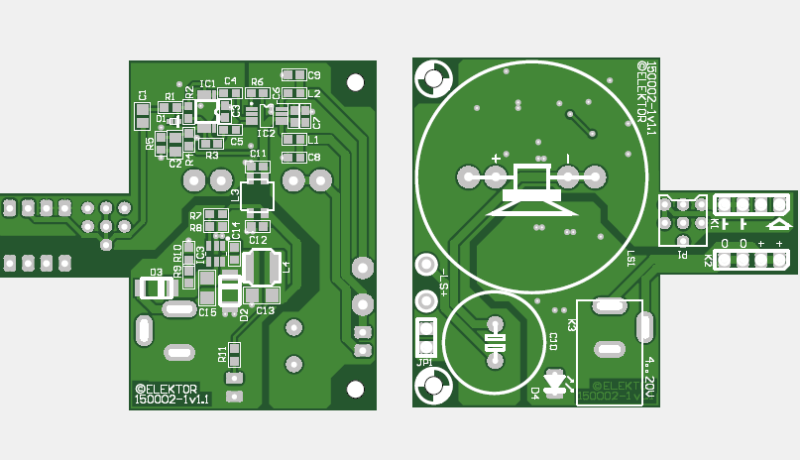
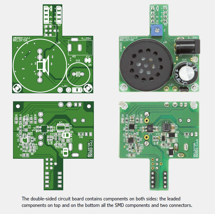
Audio T-Board (July/Aug 2015)
When experimenting with analog circuits on a breadboard, a small audio amplifier with corresponding speaker can often help make signals audible. The T-board is a solution. As Ton Giesberts explains, a compact circuit board accommodates a class-D amplifier, a DC/DC converter, and a small loudspeaker.
The circuit board contains components on both sides: the leaded components (top) and the SMD components and two connectors (bottom).
“The circuit board for the audio T-board is double-sided, both the layout as well as the mounted components,” he notes. “All the leaded components are on the top side, only the connectors K1 and K2 are on the underside (you plug these into the breadboard later). All the SMD components are on the bottom.”
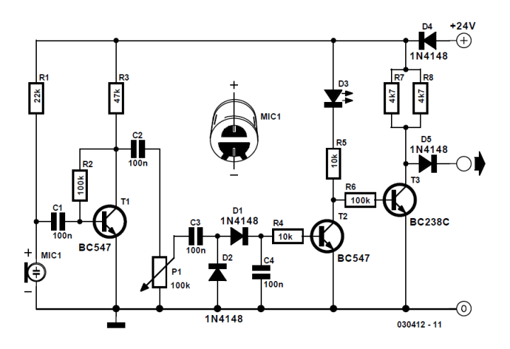
Acoustic Sensor (July/Aug 2004)
The acoustic sensor presented here was originally developed for an industrial application (i.e., to monitor a siren), but it could be used in other settings. The sensor connections are protected against polarity reversal and short-circuits, the 24 V supply voltage is suitable for industrial use, and the output of the sensor swings over the supply voltage range.
The circuit includes an electret microphone, an amplifier, attenuator, rectifier and a switching stage.
"The circuit consists of an electret microphone, an amplifier, attenuator, rectifier and a switching stage," the designer explains. "MIC1 is supplied with a current of 1 mA by R9. T1 amplifies the signal, decoupled from the supply by C1, to about 1 Vpp. R7 sets the collector current of T1 to a maximum of 0.5 mA. The operating point is set by feedback resistor R8."
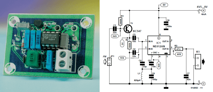
Alignment-Free FM Detector (July/Aug 2001)
The design presented here is a 455-kHz quadrature detector for narrow-band FM signals. It comes with two important advantages: it is pleasantly simple, and it does not require any alignment. An NE612 IC, which is a double-balanced mixer with oscillator in an eight-pin DIL package, sits at the heart of the circuit.
The FM detector.
“This circuit works best with an input signal level of 0.5 - 2 Vpp,” the designer explains. “Since it is linear over a very wide range (420–500 kHz), it does not need alignment, and normal tolerance variations in the values of the inductance and capacitance in the resonant circuit have little effect. The output level varies by approximately 1 V over the working range, so the detection sensitivity is around 13 mV/kHz. This is adequate for most narrow-band FM applications with an intermediate frequency of 455 kHz.”
Subscribe
Tag alert: Subscribe to the tag Battery and you will receive an e-mail as soon as a new item about it is published on our website!
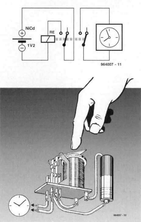
NiCd Battery Capacity Tester (July/Aug 1996)
In the summer of 1996, Elektor published an updated version of a NiCd battery tester published a year prior. The enhanced circuit improves on the original design by using a rewound relay to stop the discharging automatically at about 1 V. This prevents the deep discharging of the battery.
NiCd battery capacity tester.
“The novelty of the present version is that the battery is discharged across a relay coil rather than a resistor, while it powers the clock via the relay contacts,” the designer notes. “The timer created in this way is started by pressing the relay armature so that the contacts uphold the coil current.”
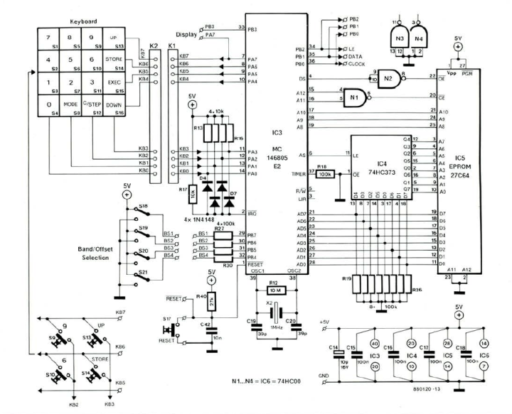
Microprocessor-Controlled Radio Synthesizer (July/Aug 1988)
The interesting synthesizer in this article features a six-digit display and a 16-position keyboard that allows direct frequency entry, channel or frequency increment or decrement, as well as the storing and recalling of 30 frequencies. Coverage of the MW, SW and FM bands are provided. Refer to the nearby circuit diagram of the microprocessor-based controller and the keyboard.
The microprocessor-based controller and the keyboard.
“The microprocessor used is the CMOS Type MC146805E2 from Motorola, which offers powerful bit manipulation instructions, useful for this type of application,” P. Topping explains. “It also has a stand-by (power-down) mode in which the clock is stopped.”
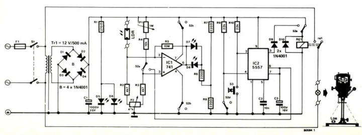
Exposure meter and Development Timer (July/Aug 1980)
Back in the late 1970s and early 1980s, exposure meters and development meters were hot topics. But, as Elektor explained in the summer of 1980, “it is very rare to find an article covering both devices at the same time. For this reason a combination design is presented here.” Check out the design.
Exposure meter and development timer.
“As usual an LDR (light-dependent resistor) has been included in the bridge circuit of the exposure meter. The amount of light falling on the LDR determines the degree of imbalance in the bridge network. During measurement, relay Ref is activated via S2e and the and 100%. The control voltage may be anywhere between 0 V and 1.5 V less than the supply voltage. When the LM 324 is used, the supply enlarger is turned on. Balance is then restored manually by adjusting potentiometer P1. The final value of P1 will correspond to the exposure time required.”
More Engineering Coming Soon!
Join us next month when we highlight more classic Elektor articles, projects, and engineering tutorials. And don’t forget to share your thoughts in the comments section below. The engineering continues!
Read full article
Hide full article
Add a rating to this article
★★★★★
★★★★★
Page 1 / 1
Login
No account yet?Register for free!
Forgot password?
Please enter your email address. Instructions for resetting the password will be emailed to you now.

Discussion (1 comment)