
J2B Synthesizer [140182]
This is a port of the Soulsby Atmegatron 8-bit monophonic synthesizer to the Elektor J2B LPC1343 ARM Cortex-M3 board. The Atmegatron is quite a nice design with everything you need fitting in 32KB of flash memory.
This is a port of the Soulsby Atmegatron 8-bit monophonic synthesizer to the Elektor J2B LPC1343 ARM Cortex-M3 board. The Atmegatron is quite a nice design with everything you need fitting in 32KB of flash memory.
New firmwares Atmegadrum, Atcyclotron & Delayertron (see below)!
The original Atmegatron is based on an 8-bit, 32 KB flash memory ATmega328 and the firmware is available as an open source Arduino sketch. The J2B board has a 32-bit LPC1343 ARM Cortex-M3 processor with 32 KB flash memory.
The Atmegatron has two rotary encoders, eight potentiometers and a pushbutton. Two potentiometers are for volume and bass boost, the others control the synthesizer itself. The J2B board can have up to nine rotary encoders, or eight plus a pushbutton.
The Atmegatron uses a bunch of bi-color LEDs to interface with the user. The J2B can have an LCD.
The Atmegatron uses PWM to produce its sound, the J2B has excellent PWM capabilities.
Based on the previous observations, porting the Atmegatron to the J2B should not be a huge task, which is why I started doing it. The most daunting task was to replace the analog potentiometers by rotary encoders while keeping the same feel. Two rotary encoders replicate the Atmegatron encoders, six others simulate the potentiometers. The bi-color LEDs are replaced by a 2x16 LCD, but I added two bi-color LEDs to indicate the red/green modes of the synthesizer.
The port of the firmware is almost completed. The synth engine works fine, but I still have to add EEPROM interfacing and I want to improve the way the values of the six "potentiometers" are displayed.
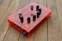
The photo below shows my prototype with the MIDI input sticking out from under the LCD. The prototyping PCB has a basic anti-aliasing filter that drives a small loudspeaker.
I designed a PCB that plugs onto the back of the J2B. The main reason for this is that the encoders on the J2B are too close together for a comfy control surface. On this mother PCB I have also placed a fifth-order Chebychev filter, an amplifier with volume control (I ditched the bass boost), a MIDI interface (in/out) and an EEPROM because the LPC1343 does not have one. It is needed to store patches. The sandwich is supposed to fit in a cheap plastic enclosure (but I will get a hard time drilling it properly).
A cool thing of the J2B is its built-in USB capabilities making it possible to update the firmware from any Windows PC simply by copying a file to the board which is seen as an external drive. No programmer needed at all.
PWM capabilities of the LPC1343 are a bit better than those of the ATmega328, which allowed me to increase the sample frequency and gain a bit, making it a 9-bit synthesizer. So, in theory, the sound quality of the J2B synth should be a little better than the Atmegatron.
I have not yet tried to implement USB serial port or MIDI functions, but I might do that later to simplify patch storage on a computer. Now it uses MIDI sysex for that.
Since I started porting the Atmegatron, Soulsby released new firmware for a drum machine on the same platform. I guess I will have to port that too (even though I don't like the way it sounds too much).
The PCB has been ordered.
Of course, once finished, the J2B Synthesizer will be open source too.
Update 23/7/2014
The PCB has arrived and I have started assembling it. Being a cheapskate I made an effort of designing a single-sided PCB, which is great. Except for one thing: single-sided PCBs don't have solder pads on two sides, which is very inconvenient when you have to solder many pin headers on the solder side...
I must be honest, the mechanical situation is horrible. First of all, I didn't take into account the height of the MIDI connectors and now they interfere with your fingers when you manipulate two encoders. 3D modelling could have avoided this.
Secondly, there are so much connections between the encoder board and the J2B board that it makes assembly almost impossible. I sort of expected this, but not that it would be that bad.
A third problem is the limited height of the encoders compared to the height of the LCD, making it pretty hard to find a good enclosure where the encoders stick out enough for fitting a knob and where the LCD is flush. Finding compatible encoders with longer shafts or shaft extenders is very hard.
Because of this mechanical disaster I have decided to start from scratch. Instead of trying to use the J2B board at all cost I will do a new design that integrates everything on one PCB. Well, not everything, I will do a small second PCB for the MIDI connectors so that it can be mounted lower.
The new design will be SMD instead of through-hole and I will probably move to an LPC1347FBD48 because it has twice the flash memory and 4KB of EEPROM. It features the same USB thumb drive method for firmware programming as the LPC1343 on the J2B board.
For the LCD I have found a thinner (and cheaper and slightly smaller) solution in the shape of an I2C LCD (Farnell 2063208) that is only 6.3 mm thick.
I have attached the Eagle files and LPCXpresso project of my first attempt. This should work on a J2B board. If you don't care about the tight spacing of the encoders I suggest you mount them on the J2B board.
On to version 2...
Update 21/8/2014
Back from holidays, I have redrawn the PCB and ordered it at Eurocircuits. Actually there are two PCBs now, one small PCB with the MIDI interface on it and a bigger PCB with the rest of the circuit.
The MCU is now an LPC1347 and I added an audio channel hoping that the MCU can cope with it. This would make the synthesizer in a 2-channel PWM audio platform. The single channel LM386 output amplifier has been replaced by a two-channel TDA1308.
Feature creep made me change the way I connected the rotary encoders. They have now RC glitch filters (from the datasheet) that should allow me to simplify and speed up the keyboard scanning algorithm. But, more important, on six of them there are now jumper resistors so that the encoders may be replaced by potentiometers connected to the MCU's AD inputs 0, 1, 3, 5, 6, 7.
The new design files are attached below.
Update 1/9/2014
PCB V2 has arrived, see photographs below. At a first glance there do not seem to be many obvious mistakes.
BTW, I renamed the synth to J:B (instead of J2B) where the two dots of the colon (':') represent the 2. But what the heck does J2B stand for??? Ideas, anyone?
Update 2/9/2014
Completed the assembly of the PCB V2, see photographs below. I found a few small footprint errors and the silk screen needs some rework to improve its clarity.
Now I need to find some screws to fix the assembly in the enclosure and drill the top cover. That's a tough one for me as I am not a very precise mechanic.
First connection to the PC is promising. The LEDs came on together with the backlight of the LCD and the PC started installing the driver for the MCU. It was slow, but after a disconnect-reconnect a new thumbdrive became visible. This means that I now can start working on the firmware.
ToDo: I²C LCD driver, EEPROM storage of parameters, second audio channel (will it be possible?), etc.
Update 3/9/2014
Validated the mechanical side of the project (see photos below). I am more than pleasantly surprised by the result of my drilling. If I can pull this off, anyone can.
The pushbutton turned out to be the most difficult as it is a bit higher than the rotary encoders. With the cap it is even higher. The cap has to go under the cover otherwise it will fall off (it has a special rim for that). Luckily the enclosure is 2.5 mm thick there which leaves enough room to drill the hole larger on the inside than on the outside allowing a perfect fit.
I used 3x25 mm screws from Castorama (Diall single thread woodscrew yellow passivated steel, round head, pozidrive, ref 50.34.20) to fix the PCB in the enclosure. As standoffs I cut four nylon screw plugs to 17mm and two to 15mm.
Update 11/9/2014
- implement EEPROM patch storage
- create clever LCD characters to clearly show which control does what
Update 12/9/2014: video!
- Tempo (60-255 bpm)
- Pitch (0-255), pressing it will get you 119, which corresponds to a sample rate of 8 kHz.
- Pitch LFO level (0-255), setting this value too high together with the pitch will crash the synthesizer because there is not yet a pitch limiter.
- Pitch LFO speed (0-15)
- Instrument delay (0-7), this is a per instrument value. It adds an echo to the instument, quite a nice effect
- Insturment volume (0-7), this is a per instrument value and allows you to mix your drum kit.
- line 1: instrument name, volume and delay
- line 2: hits for the selected instrument
Build This Project
Bring this design to life with the Elektor PCB Service, powered by Eurocircuits. Upload the project files and order professionally manufactured PCBs or assembled boards through a proven European production platform.
Supporting KiCad, Eagle, Gerber, and ODB++ formats, the service is suitable for everything from prototypes and validation builds to series production and volume manufacturing.
Made in Europe. Fast. Reliable. Professional.
Discussion (9 comments)