
Nostalgic MK484 MW/LW Radio
on

Traditionally, building a radio receiver is among the more rewarding electronics projects. This receiver is based on an MK484 IC for the AM detector, and the venerable LM386 as the audio amplifier is by no means a novelty. Still, the project is perfect for experimenting with radio reception in the medium-wave (MW) band, despite being increasingly noise-ridden and vacated by broadcast stations.
How It Works
In the circuit diagram shown in Figure 1, three RF stages permit the reception and detection of AM radio signals in the MW band (usually 500-1600 kHz). T1, a type J310 junction FET, provides positive feedback for the antenna tuning circuit. The feedback limits coil damping, increases sensitivity, and narrows the radio’s overall bandwidth. The antenna, L1, consists of a 120-200 mm long, 10 mm diameter ferrite rod holding a coil with 55 turns of 0.2 mm diameter (~ #24 AWG) enameled copper wire (ECW), close-wound. CV1 is a mica- or air-spaced 500 pF tuning capacitor providing a frequency range that matches the MW band. The tuning range can be extended down to about 150 kHz by closing the band switch S1.
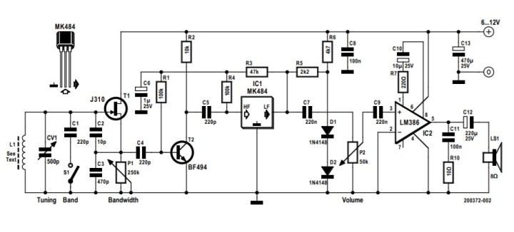
The second stage, comprising of a BF494 (T2), increases the receiver sensitivity and amplifies the MW signal for the input of the third stage at IC1, an MK484. This 3-pin integrated circuit, originally launched as the type ZN484 by Ferranti in 1972 (!) contains a complete RF amplifier, a detector, and AGC circuitry, making it one of the most popular solutions for building straightforward AM-receivers. Although the original ZN41x-series devices are long since obsolete, modern equivalents of the original 3-pin ZN414 are available, such as the MK484.
Lastly, we have the good-old LM386 (IC2) acting as an audio amplifier and loudspeaker driver, complete with the prescribed Boucherot network formed by C11 and R10. The ‘386 is sure to ring a bell with many readers.
Reception is optimal with bandwidth control P1 correctly set — simply make the adjustment by ear. The tuning range can be extended down to LW with a fixed capacitor, C1, connected in-circuit by S1. With the additional damping this introduces, the positive feedback at low frequencies may drop excessively. Fortunately, this can be compensated for by using a smaller value for capacitor C3. Some tuning, tweaking, and experimenting may be required to get it just right for MW and LW. A larger value for C1 can also help to extend the tuning range. At frequencies higher than ‘official MW,’ i.e., above 1.6 MHz or so, you’re unlikely to find any (legal) AM stations. By mounting two ferrite rods side-by-side, the cheap and simple antenna can be improved in both directivity and selectivity.
Specifications
The receiver operates from a 6-12 VDC supply and a 9 V battery is ideal. Typical current consumption is in the range of a few milliamps. At full audio power, a few hundred milliamps are required. During evening hours, under good propagation conditions, reception in the MW band is optimal, and stations as distant as 1000 km can be heard using the ferrite antenna only!
Want More on Radio-Related Content?
Elektor turned 60 this year. Since 1961, we have published numerous articles about radio-related projects over the years. Here are few recommendations.
- F. Parzer, "FM Radio with RDS: A top HAT project for the Raspberry Pi," Elektor 1/2019.
- B. Kainka, "The Elektor DSP radio: DSP world receiver with USB interface," Elektor 7/2010.
- B. Kainka, "The ATM18 Radio Computer: Using the SI4735 DSP radio chip," Elektor 2/2010.
- H. Kipp, "Elektor Internet Radio (EIR): Listening to radio programmes with the latest ICs," Elektor 4/2008.
- M.S. Dhingra, "Solar-power MW radio," Elektor 11/1990.
- Elektor Team, "4 W car radio amplifier," Elektor 7/1977.
Discussion (2 comments)