
Preamplifier 2012 (1) - introduction and line-in/tone/volume board (110650)
Audio lovers, sit up. Besides presenting a truly high end audio control preamplifier for home construction, this article series also aims to show how low-impedance design and multiple-amplifier techniques can be used to significantly reduce the noise levels in analogue circuitry.
Audio lovers, sit up. Besides presenting a truly high end audio control preamplifier for home construction, this article series also aims to show how low-impedance design and multiple-amplifier techniques can be used to significantly reduce the noise levels in analogue circuitry. The result of the design effort is a top-notch preamp that’s brilliant not just sonically but also in terms of cost/performance ratio.
Published in Elektor Magazine, no. 424, April 2012
By Douglas Self
It is now some time since I published a preamplifier design — the Precision Preamp in 1996. Inevitably technology has moved on. In that design the recording output level was as low as 150 mVrms to get a good disc input overload margin, the amplitude being well within the reach of the average tape recorder input level control. Nowadays most audio line inputs will be from digital sources, typically at 1 Vrms unbalanced or 2 Vrms balanced, and recognition of that requires a completely new design, especially in the MM/MC phono section.
The preamplifier described here demonstrates how very low noise levels can be achieved in analogue circuitry without using exotic parts. It was originally conceived as being entirely made up of 5532 opamps, like the earlier Elektor 5532 OpAmplifier but during the design process it became clear that adding a few LM4562s (which are now a good deal cheaper than they used to be) would avoid some awkward compromises on distortion performance, because of their superior load-driving ability.
In addition, the preamplifier has a very versatile MC/MM phono input stage with gain-switching, which I believe can optimally handle any cartridge on the market; this is guided by an innovative level indicator that provides more information than just on/off from one LED and does away with the need for bar-graph metering.
A block diagram of the proposed preamplifier is shown in Figure 1. In practice, the project is divided into several circuit boards, each of which will be discussed separately starting this month with the circuitry comprising the line amplifier, tone control, volume control, and output stage.
Noise of three kinds
There are three main causes of electronic noise in analogue circuitry: Johnson noise from resistors, and current and voltage noise from semiconductors.
All resistances (including those forming an integral part of other components, such as the base spreading resistance of a bipolar transistor) generate Johnson noise at a level that depends on the resistance and the absolute temperature. There is usually little you can do about the ambient temperature, but the resistance is under your control. Johnson noise can therefore be minimised by Low Impedance Design, in other words keeping the circuit impedances as low as possible.
In the early 1970s audio circuitry commonly used 25 kΩ or 50 kΩ potentiometers and associated components of proportionally high impedance, mainly because the discrete transistor circuitry of early opamps used had poor load-driving abilities. When the (NE)5532 appeared, and equally importantly, came down to a reasonable price, it was possible to reduce impedance levels and use 10 kΩ pots. This may not seem very ambitious when you consider that a 5532 can drive about 800 Ω while keeping its good distortion performance, but the pot value does not always give a good idea of, for example, the input impedance of the circuit block in which it is used. It is not widely known that a standard Baxandall tone control constructed with two 10 kΩ pots has an input impedance that can easily fall to less than 1 kΩ. There is a cunning way round this problem; the Bass and Treble tone control networks can be driven separately; more on this below.
Fixed resistors are available in almost any value, but the pot values available are much more restricted, and the lowest practical value, in that two-gang pots are available for stereo, is 1 kΩ.
Current noise is associated with opamp inputs. It only turns into voltage noise when it flows through an impedance, so it can be reduced by Low Impedance Design. The use of low value pots also means that opamp bias currents create less voltage drop in them and so there are less likely to be intrusive noises when the wiper is moved.
Voltage noise is the third type of noise. It is already in voltage format, being equivalent to a voltage noise generator in series with the opamp inputs, and so cannot be reduced by Low-Impedance Design. At first it seems that the only thing that can be done to minimise it to use the quietest opamps available. Opamps exist that are quieter than the 5532 or the LM4562, but they are expensive and have high current noise. A typical example is the AD797, which has the further drawback of only being available in a single package, putting the cost up more.
A better path is the powerful technique of using of multiple cheap amplifiers with their outputs summed — or to be more accurate, averaged. With two amplifiers connected in parallel, the signal gain is unchanged. Their outputs are averaged simply by connecting a low value resistance to each amplifier and taking the output from their junction. The two noise sources are uncorrelated, as they come from physically different components, so they partially cancel and the noise level drops by 3 dB(√2). The amplifier outputs are very nearly identical, so little current flows from one opamp to another and distortion is not compromised. The combining resistor values are so low (typically 10 Ω) that their Johnson noise is negligible. This strategy can be repeated by using four amplifiers, giving a signal-to-noise improvement of 6 dB, eight amplifiers give 9 dB, and so on. Obviously there are limits on how far you can take this sort of thing. Multiple opamps in parallel are also very useful for driving the low impedances of Low Impedance Design, so the two techniques work beautifully together. The Elektor 5532 OpAmplifier pretty much took this to its logical conclusion.
The multiple-amplifier approach gets unwieldy when the feedback components around each amplifier are expensive or over-numerous. To use two amplifiers in a standard Baxandall tone control you would have to use quad-gang rather than dual pots for stereo, and also duplicate all the resistors and capacitors. While this would reduce the effect of all the noise mechanisms in the circuit by √2, giving a solid 3 dB improvement, it is not an appealing scenario.
If instead you simply halved the impedance of the Baxandall network by halving the pot and resistance values and doubling the capacitor values, the situation is not equivalent. In the second case you have halved the effect of the opamp current noise flowing in the circuit impedances, and reduced the Johnson noise by root-two, but the opamp voltage noise remains unaffected and will often dominate.
Line input and balance control stage
This is a balanced input stage with gain variable over a limited range to implement the balance control function. Maximum gain is +3.7 dB and minimum gain –6.1 dB, which is more than enough for effective balance control. Gain with balance central is +0.2 dB.
Looking at the circuit diagram in Figure 2 and discussing the left (L) channel only,IC2A is the basic balanced amplifier; it is an LM4562 for low voltage noise and good driving ability. The resistances around it are low to reduce noise so it is fed by unity-gain buffers IC1A/B which give a high input impedance of 50 kΩ that improves the CMRR. Note the EMC filters R1-C1 and R2-C2 and the very start of the circuitry. The stage gain is set by 1 kΩ pot P1A, the negative feedback to IC2A being applied through two parallel unity-gain buffers IC3A/B so the variation in output impedance of the gain-control network will not degrade the CMRR. The dual buffers reduce noise and give also more drive capability. In this stage combining the buffer outputs is simple because the feedback resistance can be split into two halves; R8 and R9. This requires R11 and R12 to be paralleled to get exactly the right resistance value and so preserve the CMRR.
The noise output of this stage is very low: –109 dBu with the balance control central; –106 dBu at maximum gain and –116 dBu at minimum gain. (all 22 Hz – 22 kHz, rms)
The tone control stage
It is not obvious but this is (mostly) a conventional Baxandall tone-control. Once more 1 kΩ pots are used, requiring large capacitors to set the turnover frequencies, C7 at 1 μF sets the bass frequency and C8, C9 at 100 nF set the treble frequency. The cut/boost is ±10 dB maximum for both. The stage has a low input impedance, especially when set to boost; to deal with this the Bass and Treble parts of the tone-control network are driven separately. The Treble network C9-P3B-C8 is driven directly by IC2A in the previous stage, while the Bass network R15-C7-P2B-R14 is driven separately by the extra unity-gain buffer IC2B, the other half of the LM4562 in the line input stage. I call this a split-drive Baxandall circuit.
The Treble network is the two-capacitor version rather than the one-capacitor types; this has the advantage that the treble pot is uncoupled from the circuit at low frequencies and reduces the loading.
The main tone-control opamp is IC4A, which drives the Treble feedback path directly, while unity-gain buffer IC4B gives separate drive to the Bass feedback path. Polypropylene capacitors are strongly recommended as they are free from distortion while polyester types show significant non-linearity. Unfortunately they are also physically larger and more expensive, but well worth it in my view.
The noise output of the tone-control stage alone is only –113 dBu with controls set to flat.
Relays RE1 and REe2 implement a tone control defeat function by enabling the active volume control stage to be driven directly from IC2A. To prevent clicks and other noises when the relays switch over, R18 and R58 have been added, effectively keeping up the bias to IC9B and IC18A. To keep crosstalk down to a minimum each channel has its own relay. As a bonus, two contacts can be connected in parallel, preventing any risk of signal degradation and at the same time increasing life span.
Active volume control stage
The volume control is of the active Baxandall type which gives low noise at low volume settings and also synthesises a quasi-logarithmic control law from a linear pot, giving much superior channel balance. Maximum gain is +16 dB, with 0 dB obtained with the control central. The input impedance of the volume control stage, implemented with another 1 kΩpot P4A, falls to low values at high volume settings. It is therefore driven by the ‘load-splitting arrangement’ where buffer IC9B provides half of the drive from the tone-control stage. Resistors R19, R20 ensure that IC4A and IC9B share the load between them.
The conventional Baxandall active volume control as in [1] uses a single buffer and one inverting amplifier, such as IC5A and IC5B. Here four of these circuits are used in parallel to reduce noise by partial cancellation of the uncorrelated noise from the four amplifier paths, and to give sufficient drive capability to drive the back end of the 1 kΩvolume pot. The use of four paths reduces the noise by 6 dB. The multiple shunt amplifiers have no common-mode voltage on their inputs and so no CM distortion, and the associated buffers handle less than a third of the output voltage so stage distortion is very low. The enhanced drive capability means that it is not necessary to resort to LM4562s which still get a little expensive if you are using a lot of them. Four 10 Ω resistors R29-R32 are used to average the four outputs.
At sustained maximum sinewave output (about 10 Vrms) the volume pot gets perceptibly warm, as a consequence of the Low-Impedance Design approach. This may appear alarming but the heating is well within the specification of the hotpot. This does not occur with music signals.
The noise output of the active volume stage alone is –101 dBu at maximum gain and –109 dBu for 0 dB gain. For low gains around –20 dB, those most used in practice, noise output is about –115 dBu. Rather quiet.
Here I have quoted the noise performance for each stage separately, to demonstrate the noise-reduction techniques. In a complete preamplifier the noise levels add up as a signal goes through the system, though how this happens depends very much on the control settings.
Balanced output stage
The balanced output consists simply of a unity-gain inverter IC9A which generates the cold (phase-inverted) output. The balanced output is therefore at twice the level of the unbalanced output, as in normal hifi practice.
Construction notes
The project employs standard leaded components throughout. A high quality circuit board designed by Elektor Labs for the project is available through www.elektorPCBservice.com. The component overlay appears in Figure 3.
It is recommended to use a flip over type PCB jig. Start with low-profile components and finish with the taller ones.
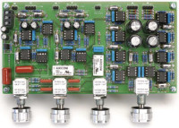
The finished board pictured in Figure 4 should be taken as an example to work from — success is guaranteed if you strive to achieve this level of perfection in construction.
Do not forget to fit JP1 for the ground through connection, a similar jumper is present on the MC/MDMM board. This allows you to determine empirically which ground connection works best. When the wiring is complete one jumper has to be fitted, or both.
Axial polystyrene caps require care in determining where to bend the legs. Their size is not standardized and subject to various tolerances compared to other parts.
Finally, on the potentiometers, plastic types from Vishay Spectrol may be used instead of cermet.
Build This Project
Bring this design to life with the Elektor PCB Service, powered by Eurocircuits. Upload the project files and order professionally manufactured PCBs or assembled boards through a proven European production platform.
Supporting KiCad, Eagle, Gerber, and ODB++ formats, the service is suitable for everything from prototypes and validation builds to series production and volume manufacturing.
Made in Europe. Fast. Reliable. Professional.
Discussion (40 comments)