
Review: IoTize Your Projects with TapNLink Wireless Primer
on
IoTize, based in Grenoble (France), specializes in adding wireless connectivity to about anything. Adding one of their interfaces to a system allows it for instance to transmit data over the internet or to be controlled remotely. It becomes part of the internet of things (IoT) — i.e., it has been “iotized”. There are other players in this field, but IoTize is different as they also provide tools to simplify visualizing and using the data captured by their modules, be it as an app on a smartphone or in the cloud. Furthermore, IoTize handles multiple wireless standards like Wi-Fi, Bluetooth and NFC (support for Sigfox has been announced). Let's take a look at how to IoTize your projects with TapNLink.
TapNLink Wireless Primer kit
All that sure sounds interesting. Low-cost evaluation kits are available to get a feel for what IoTize can do for you. Since I am notoriously hard to convince, I had a play with one of them: the TapNLink Wireless Primer kit (Figure 1). A hands-on experience is usually more revealing than a marketing brochure, now, isn’t it?
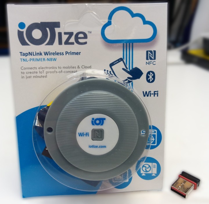
(The USB dongle is only there to help you estimate the size of the blister.)
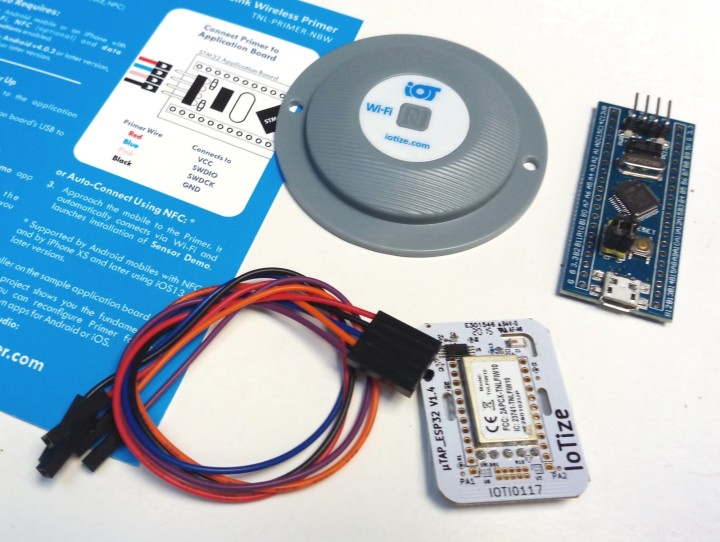
The TapNLink Wireless Primer kit comprises four parts (Figure 2):
- An IoTize µTap module;
- A small microcontroller module (Blue Pill);
- A short, colourful 5-way cable;
- A grey plastic cover.
The idea is that the small microcontroller module – an STM32 ARM Cortex-M3 board better known as Blue Pill – plays the role of the target device that must be iotized. It connects to the µTap module – a stamp-size board measuring 38 mm × 28 mm – using the cable included in the kit. The IoTize module (optionally) clips inside the plastic cover so that it can be fixed with two screws (not included) to a surface, e.g. a wall or a machine.
Two Versions
Note that there are two versions of the TapNLink Wireless Primer kit, one with NFC and Bluetooth (NB), and a second that adds Wi-Fi to the mix (NBW). NFC-only modules exist too, but not in a kit. The colour of the label on the plastic cover tells you which is which. White is with Wi-Fi, blue is without. I tried the white one, the TNL-PRIMER-NBW.
Orange Is the New Pink
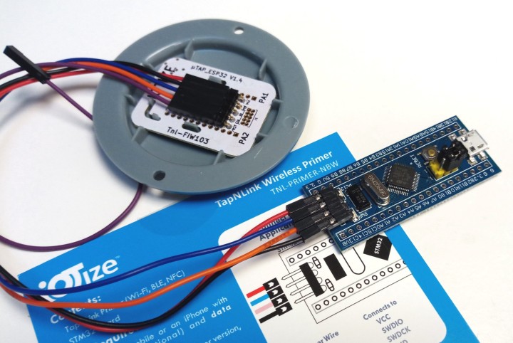
The packaging of the kit doubles as quick start guide and shows how to connect the two boards. It mentions a pink wire, but the cable in my kit didn’t have a pink wire. This is somewhat confusing as the IoTize module has a 5-pin connector whereas the STM32 board only has four pins and the labelling on the boards is not the same. The cable has a 5-way connector on one side and five loose ends on the other as they must be able to connect to any microcontroller board. It turned out that in my case the pink wire was orange. Pink is close to orange, but don’t tell that to the Dutch Royal Family. The purple wire is not connected to the STM32 board. See also Figure 3.
Power to the evaluation system is provided by connecting the STM32 module with a micro-USB cable to a computer (both not included in the kit). This is not a problem, as a computer is needed anyway.
First Steps
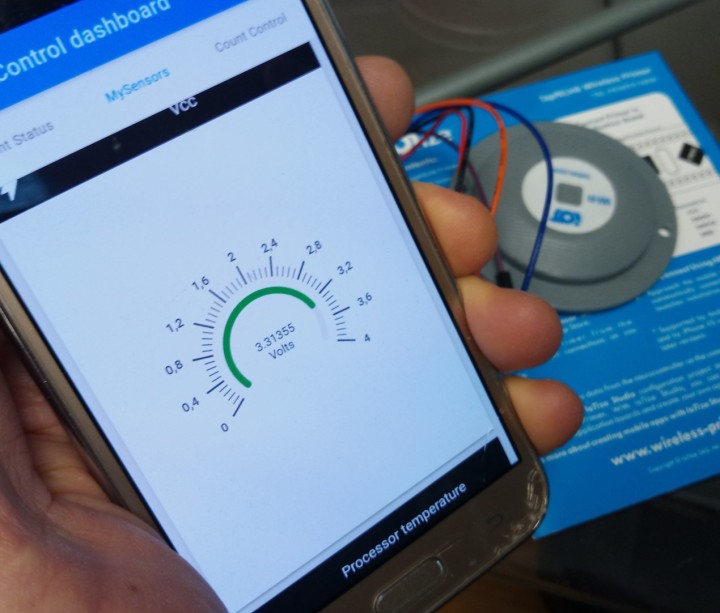
Before moving over to the computer, however, we first try the TapNLink with a smartphone with NFC. If you have one and you hold it over the µTap module, the tag is detected, and you are taken to the IoTize demo app in the Google Play store. Install the app and open it. If you have Bluetooth activated, you can now connect to the device (you may first have to pair it to your phone before it can be used). Once connected, you will see a counter and an LED control. On the MySensors tab, you can see the value of the supply voltage of the STM32 board (Figure 4), and, if you slide upwards, you can also see the temperature of the STM32 processor.
You Must Log In to Control the LED
The Count Control tab has a slider to set the blink rate of LED PC13 on the STM32 board. To make it work you must first log into the IoTize module. Do this by tapping the Supervision option in the app’s menu (the icon in the top left corner). Enter ‘admin’ for both the user and password. Go back to the slider and change the LED's blink rate.
Wi-Fi Works Too
Instead of doing this over Bluetooth, you can achieve the exact same result over Wi-Fi. To use Wi-Fi, connect to the ‘Sensor demo_xxxxx’ network (where xxxxx represents a 5-digit number). They forgot to mention it in the documentation, at least I didn’t see it, but the default password is ‘ABCD1234’ (instead of ‘12345678’ like everybody else).
Now that we know that the evaluation system is working, we can go a step further and try to modify the application. Detailed tutorials to do so are available on the IoTize website, together with a lot of other useful documents. As I managed to go through them, you too will probably succeed. More interesting is having a closer look at how things work.
Two Applications
Actually, there are two applications: one running on the Blue Pill and the other running on the µTap board.
This is probably a good moment to explain in more detail how the two boards communicate. Usually, in a setup like this, both applications know that the other exists and both have at least some knowledge about what kind of data the other expects and what functions it has. Not here. The STM32 board has no idea about the existence of the IoTize module and vice versa, yet they talk to each other. So how is this possible?
It's a Debugger?
The trick is that the µTap module kind of behaves like a debugger. It connects to the debug target, so to speak, and, like a debugger, inspects the target’s registers and memory. It can also modify these. The target is the STM32 module. For this to work, the target must have a compatible interface. Currently only ARM’s SWD debug protocol is supported, but for other microcontrollers there is the proprietary Secure Serial Software Protocol or S3P. Not only can this be implemented on any microcontroller that has two I/O ports to spare (a library for Arduino is avbailable at GitHub), it also features secure communication. Because of this, even on MCUs that do speak SWD, S3P is the preferred way to go.
Like a debugger, the IoTize application needs a list or memory map of the variables used by the target application. It can then request the target to send the contents of the variable stored at address A or tell it to write something to address B. This list must be provided by the compiler of the target application and is usually contained in the .ELF file (and not in the .HEX file).
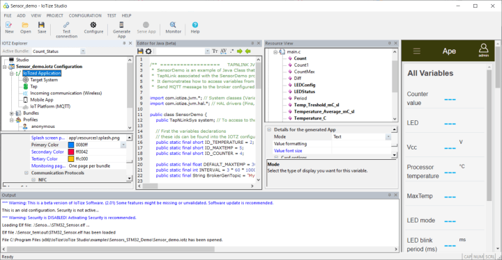
Drag 'n' Drop Programming with IoTize Studio
IoTize Studio, the free graphical integrated development environment (IDE) for IoTize boards, makes this process easy (Figure 5). After importing the target’s .ELF file, it knows the names and addresses of the variables and registers available on the target. To the application developer, they are like any other variable. What this means is that the µTap application developer does not need access to the target system. He or she only needs to know what the imported variables are for (proper naming helps a lot here). On the other hand, it does mean that when the target application is recompiled and its symbol table changes, the IoTize app must be recompiled too.
Now, IoTize Studio goes quite a bit further as it makes programming the IoTize board a matter of dragging and dropping users on target variables combined in bundles. The application is generated automatically, including any web pages that it may need. And, while at it, it can also produce the Android app to run on your phone to interact with the µTap board. Just click the Generate App button. This last feature is possible because the people from IoTize installed the Android app development system on their servers somewhere in the cloud. Therefore, you, the user, do not have to install anything else but IoTize Studio. And although an account to access their cloud is required for this, it is free.
Security Above All
Now there remains one important thing to highlight, and that is security. It already came along a few times, but we did not go into it. The IoTize ecosystem (at Elektor we are allowed to use this word once per article) has data security at its heart. It is embedded in the secure serial software communication protocol (S3P) between target and host (not in SWD), and it is in IoTize application design as well.
First Commandment of IoT: Users Have Rights
Every IoTize application has users, and these users have rights. An IoTize application can have multiple users that have different rights. Some are administrator and are allowed to do whatever they like while others may only see some parameters, a temperature for instance, or a voltage. We already saw security in action when we wanted to change the blink rate of the LED of the demo application. The default user is not allowed to do this, you must log in first.
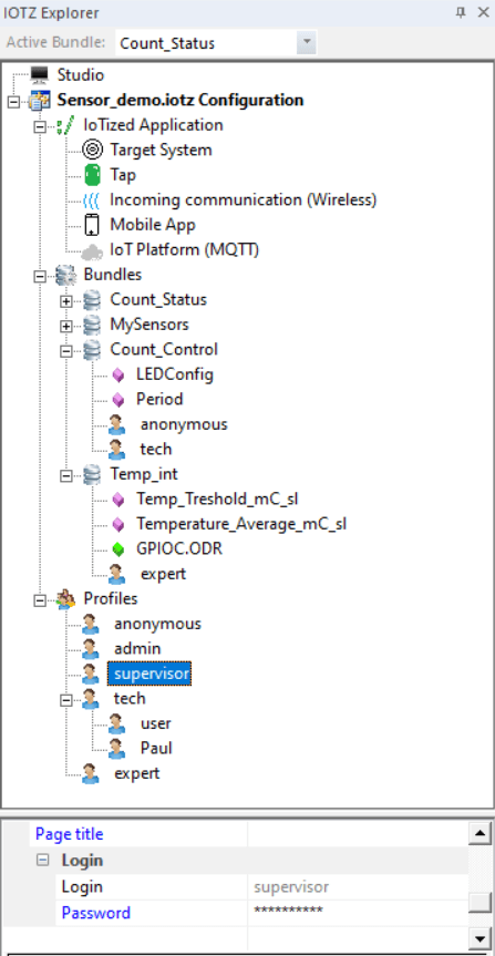
As a result, when creating an application in IoTize Studio, besides designing the hot, funky graphical interface, you must also define users or profiles and give them rights. The variables needed by the application together with the profiles (users) that are allowed to access them are combined into so-called bundles (Figure 6). The bundles translate to tabs or pages in the app and so every profile has its own user interface. As this is all a matter of dragging and dropping, it is very easy to see what users are allowed to do and see. User management therefore is pretty simple, even for me.
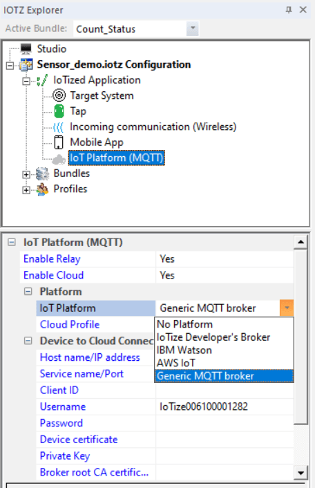
Cloud Support
Finally, but not unimportant, there is cloud support. It is possible for the mobile app to communicate via MQTT with a cloud dashboard generated based on the configuration of the mobile app. This is done using IoTize Studio and server-based tools. Dashboards can be used on the IoTize development servers (which you can access thanks to your account for compiling Android apps, see above) and this is compatible with leading cloud platforms like AWS, Watson, Azure, and more.
Summing Up
This brings us to the end of this review. Summing up, we can say that the people of IoTize have come up with an original and efficient solution to add wireless communication to any microcontroller-based system that has two GPIO pins to spare. Not only does their solution support multiple wireless standards like NFC, Bluetooth, and Wi-Fi, it also comes with data security built-in, which today is probably the most important thing for a device connected to the internet.
Cloud support has not been forgotten either thanks to MQTT and automatically generated dashboards. And because time to market is essential, IoTize has put a lot of effort in making it all easy. IoTize Studio with its drag ‘n’ drop programming and the cloud-based Android app compiler and cloud dashboard tools make it a breeze to get started. Finally, it wasn’t mentioned yet, but IoTize Studio and the boards are supported by an extensive online documentation system.
Just so that we can end on a negative note ;-), I don’t like the colour of the plastic cover much.
Webinar
Learn about the latest features of TapNLink Primers. Add NFC, WiFi or Bluetooth interfaces to your applications for ARM Cortex-M based microcontrollers. Create mobile apps to receive data from and control your application.
Demo tools:
- TapNLink-PRIMER for NFC, Bluetooth and WiFi
- IoTize Studio configuration software
- Ionic cross-platform app development tools for Android
Language: English
Max. Participants: 50
Register now at https://www.iotize.com/tapnlink-webinar.html
Discussion (0 comments)