
Small Circuits Revival — Episode 1
on
Energy Efficient Relay
idea: Michael A. Shustov (Russia) and Andrey M. Shustov (Germany)
The relay circuits discussed here can be connected in series with a load (lamp) and a series of normally-closed pushbuttons. When one of these switches is pressed, the lamp lights up for a certain time. After that time, the lamp will turn off automatically.
This looks a bit like the familiar stairwell lamp circuit, where you can switch on the lighting in a stairwell or corridor with the push of a button and switch it off again with the push of another button. However, the circuits described here automatically switch themselves off again - and are in principle a lot more energy-friendly.
Variant 1
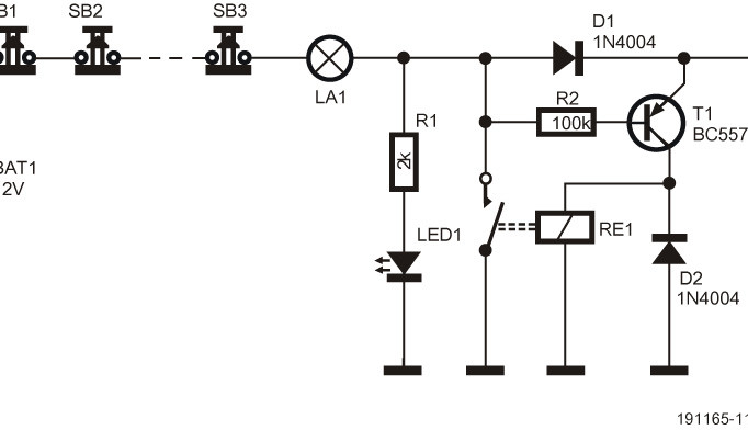
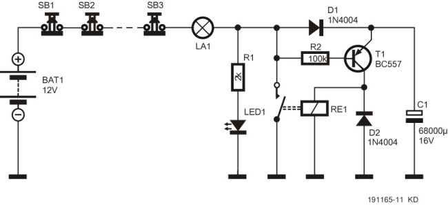
The first variant (Figure 1) is not difficult to fathom. The circuit runs off a 12 VDC source (battery, mains adapter) - and can therefore also be safely reconstructed by a beginner. Immediately after the circuit is connected, capacitor C1 will be charged by lamp LA1 and diode D1 via the series connected normal-closed pushbuttons S1...Sn (only three have been drawn). The lamp will light up for a while. LED1 indicates that the circuit is armed. For the record: the current flowing through the lamp at rest is too low to let it light up.
As soon as one of the pushbuttons is operated, no more current can flow into C1 through D1. The base of transistor T1, which via the lamp is held at + potential of the power supply, is now pulled to ground via resistor R1 and LED1. The result: the transistor switches on and capacitor C1 discharges to ground via the relay coil. The relay is energized and via the relay contact there is now enough current to keep the lamp on. Also, the charging current into C1 is interrupted.
After some time, the capacitor has discharged so much that the relay can no longer remain activated. The relay contact opens, and the initial situation is restored (whereby we quietly assume that the pushbutton is not held pressed).
For the time that the lamp remains switched on, the following approximate relationship applies:
t = 0.67 x RRelay x C1 [seconds, ohms, farads].
The EMR type mentioned in the diagram has a coil resistance of 1050 Ω; for the G6DS type it is 1200 Ω. With the former relay and a capacitor of 68.000 µF we arrive at about 40 s.
The value of resistor R1 must be chosen so that the current through LED1 is just large enough to make it light up weakly. The value mentioned in the diagram will usually suffice, but there is room for some experimentation.
A word of warning: this circuit should NOT be used for lamps that are connected to the AC power line (mains)!
The second variant will be discussed next week.
Discussion (2 comments)