
Small Circuits Revival — Episode 2
on
Energy Efficient Relay
From an idea by Michael A. Shustov (Russia) and Andrey M. Shustov (Germany)
Version 2
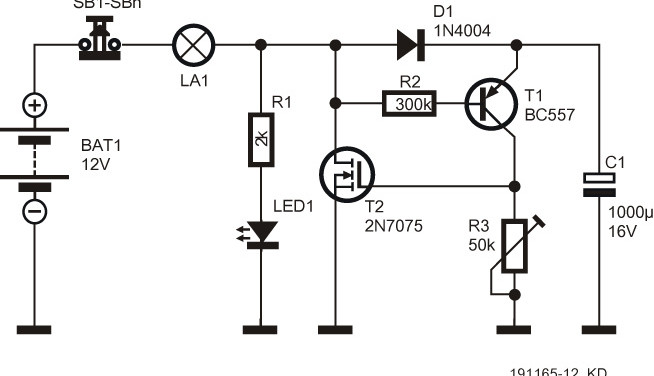
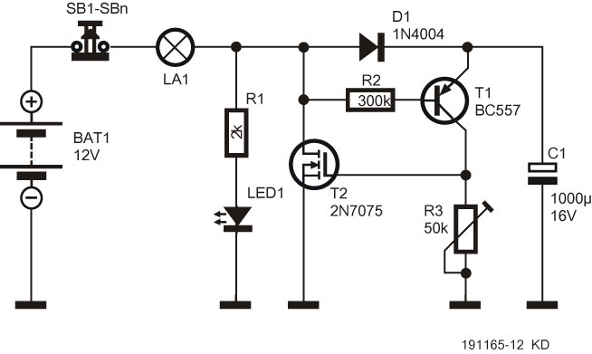
In this version (Figure 1), the electromechanical relay got replaced by a MOSFET type 2N7075 or 2N7085 as the switching element. Important: in contrast to the previous incarnation, the ‘lights-on’ time can be conveniently set using preset or potentiometer R3. Roughly speaking, 1 kΩ corresponds to 1 second, so with the value of 50 kΩ shown in the diagram, an adjustment range of 1 to 50 seconds is achieved.
The big advantage of the relayless version is that a much smaller capacitor can be used in position C1. This improves the repeatability of the circuit. The maximum current that can be switched (with sufficient cooling) is about 30 A for the 2N7075 and 20 A for the 2N7085.
Again, this version is only suitable for low-voltage direct-current applications, and should never be used for lamps connected to the AC line voltage.
Miniature switches with push-to-break action (i.e. normally-closed types) are easily available. Mains-rated switches with the same functionality are rare but they do exist - just put Google to work with the search term "impulse switch"... They might come in handy with the mains-operated version we'll be looking at next week!
Correction
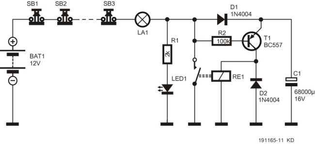
Several readers have (rightly) pointed out to us that in the schematic of the first version published in Episode 1 has an error: flyback diode D2 has ended up in the wrong place. Our apologies, of course, and thanks to the attentive readers! Below is the corrected schematic (Figure 2).
Discussion (2 comments)