
Acoustic Wave Hovering
on
In recent editions of Elektor, we have presented three small, simple circuits for magnetic levitation. It was noted that there are other methods for levitating objects, such as using acoustic waves. Instructables.com describes a DIY project designed at the University of Bristol that uses sound waves from off-the-shelf ultrasonic transducers to achieve this apparent weightlessness of small objects. The Makerfabs Acoustic Levitator DIY Kit, available from the Elektor Store, contains all the parts needed to build this so-called TinyLev project, thus saving you the trouble of searching for the components yourself, including the 3D printed frame needed to build the complete contraption.
The kit comes without documentation, but the web link in the Elektor online store guides us to the aforementioned Instructables project page. It is loaded with instructions in text, photos and even videos, and the step-by-step approach will guide you through the construction of the kit.
On this web page you can also find (links to) background information and theory on acoustic levitation; it provides good reading if you want to do more than just building and playing with the TinyLev as a gadget. In short: the levitation relies on the standing wave pattern of (in this case: two) arrays of ultrasonic transducers, each array arranged in a curved, ball-shaped ‘reflector’. The correct shape and geometry of the base with the reflectors and the positioning of the transducers are essential for the levitation effect. On the Instructables site, there are two 3D designs available for downloading and printing the base for TinyLev. The Makerfabs Acoustic Levitator kit contains a printed specimen of version V1 plus the leg that must be glued the base, ready for use.
Start Building, but First Things First
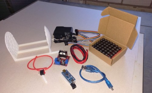
After checking the contents of the kit (Figure 1), the first thing to do is to determine the correct polarity of every single ultrasonic transducer (Step 4 … 6).
Apparently, polarity markings on ultrasonic transducers in general are not to be trusted, it is not that the MakerFabs kits contains questionable components! With 72 sounders in total, this is quite a time-consuming task. In the instructions, two methods how to do this are presented, including using the Arduino Nano board - that is also included in the Makerfabs kit - as a minimalistic ‘oscilloscope’. Testing with a standard digital multimeter is probably the easiest and fastest way to do the job: simply mark the polarity based on the initial potential on the transducer’s pins when the probes are connected. However, my auto ranging DMMs appeared not to be usable here, you need to have a meter that can be manually switched to the most sensitive voltage range and immediately reacts when the meter’s probes are connected to the transducer. Eventually, I used the Arduino Nano method. Take your time to do this, one mistake can spoil or even completely ruin the levitation effect. It is of the utmost importance that all transducers have the correct phase of the sound signal.
The Transducer Arrays
With all the transducers marked, it’s time to glue them all to the 3D printed frame. The manual on Instructables recommends the use of hot glue; for me that doesn’t work with relatively small parts, like these transducers. If you want me to make a mess of my workbench, give me a hot glue gun… I used a tube of hobby adhesive for hard plastics. Whatever you use, make sure that all markings you made on these parts point to the same direction: either all to the center or all to the outer edge of the reflector. They should fit flush into the round recesses/sockets in the base. I ended up with some spare parts, four transducers were not needed to completely fill the frame (i.e. there are 76 in the kit!). Two of them may be needed for troubleshooting, and can be used as sensors (microphones) to check the phase of the sound from all transducers individually (if things don’t work…).
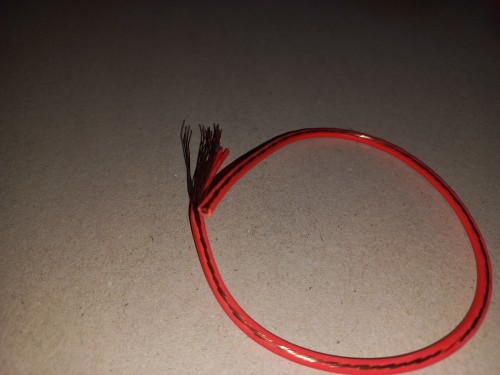
The next step, Step 8 in the instructions, is to wire the transducers. The kit contains a piece of thick, stranded wire with the isolation cut open (Figure 2), every single wire from this can be used to interconnect legs of the transducers in concentric circles.
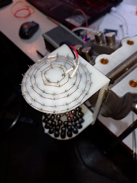
The longer red and black wires from the kit finish the wiring of the base, with the transducers arranged in two arrays of 36; the shorter wires are kept aside for the power supply wiring of the electronics in Step 15 and 16. Figure 3 shows what the wiring of one of the reflectors will look like.
Other Hardware and Software
In the following steps the other connections need to be made: between the Arduino Nano and the driver board, the power wiring, and between the driver board and the base with the transducers. The Arduino needs to be programmed of course. Download the Nano_TinyLev.ino sketch from the Instructables site, compile and upload it in the Arduino IDE.
The driver is a standard L298N dual motor driver board, in this case it provides the 40 kHz sound signals for the two transducer arrays. The procedure to make these interconnections will not be difficult for the experienced tinkerer, just follow the text and photos on Instructables which - admittedly - could have been a bit clearer at some points. The base board used for fixing the PCBs and power circuit is not included in the kit, but a 10 x 10 cm or larger piece of plywood will do.
Check, Check, Double-Check…
It is advisable to do the tests described in the instructions before the transducers are connected, especially to check for short circuits in the arrays, which would probably damage the driver board. Also, check the output signals of the driver board with an oscilloscope. Then, if you have enough confidence in your own work, that is if you are - as good as - sure that all transducers are correctly connected and working, you may save time and skip checking (the phase of) all sounders individually. You can always do that afterwards; if the levitation does not work properly, there is a good chance that the fault lies in the arrays. I had a lot of confidence in my work and that turned out to be justified: it worked straight away!
And Experiment…
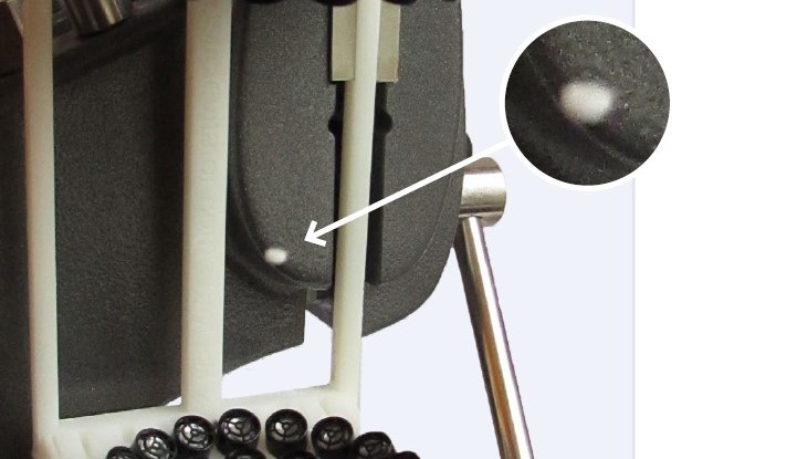
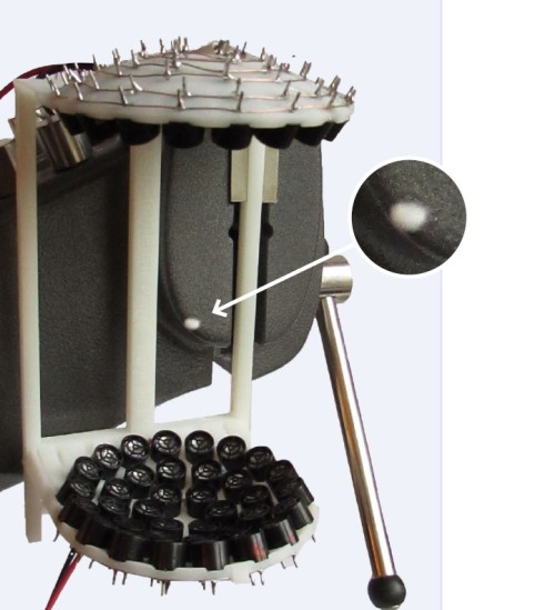
And then, it’s time to start experimenting with all kind of ‘things’ that can be levitated with the TinyLev. I didn’t spend too much on this though, I tried some rolled-up tiny pieces of paper, small plastic beads and polystyrene balls, and these were pretty easy to levitate between the transducer arrays (see Figure 4). The Instructables page also describes hovering of small (dead) insects and drops of liquid. Searching for ‘TinyLev’ on the internet, you’ll find lots of other experiments with this project that may be nice to try for yourself (or maybe they can trigger new ideas).
Hovering on Acoustic Waves
Building the TinyLev is easy to do with this MakerFab Acoustic Levitator DIY Kit. All essential parts are included and with all the information that can be found on the Instructables website and other Internet sources, it will be relatively easy to start experimenting with acoustic levitation. Do not expect to finish the construction within an hour or so. I spent quite some time only to check and mark the transducers and to solder the arrays. And with the rest, I even skipped some steps that were not absolutely necessary to get the levitation working on my workbench. Don’t rush things, though: one mistake — especially in the transducer arrays — may cost a lot of time to troubleshoot and fix! If you have done it right, the hard work will be rewarded with a huge ‘wow’-feeling when you see the first object hovering on the TinyLev’s acoustic waves!
Questions or Comments?
Do you have any technical questions or comments about this article? Contact the author at Luc.Lemmens@elektor.com or contact the Elektor team at editor@elektor.com.
Good to hear!
The frequency of ultrasound is above the human hearing limit, hence the name. In this case, we are talking about 40 kHz, about a factor of two higher than the highest tone we can perceive. At best, we will hear a click or short crackle when switching on the TinyLev, but other creatures, like your pets, can hear it and may react strongly to it. The author’s cats don’t seem to mind, but they only react to food-related sounds anyway.
Discussion (0 comments)