
Berry Good: GPS and Sensors for Raspberry Pi & Co.
on
Thanks to I2C and SPI, most of the signal conditioning otherwise necessary for connecting sensors to microcontrollers is eliminated. Modern turnkey sensors deliver their data ready-packaged via a standardised serial bus. The problem that remains is the tiny packaging used since many of these sensors are intended for use in smartphones and other handheld and wearable devices. As a result, they are packaged in BGA or other tiny packages that are not very easy to assemble by hand (see box The problem with BGAs). In the case of small series production it would be uneconomical to use ready-made evaluation boards that contain a main controller plus all the sensor technology. Instead, expansion boards, such as the Berry collection of devices, are an attractive alternative.
Welcome to the Berry Family!
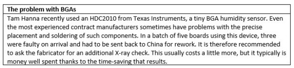
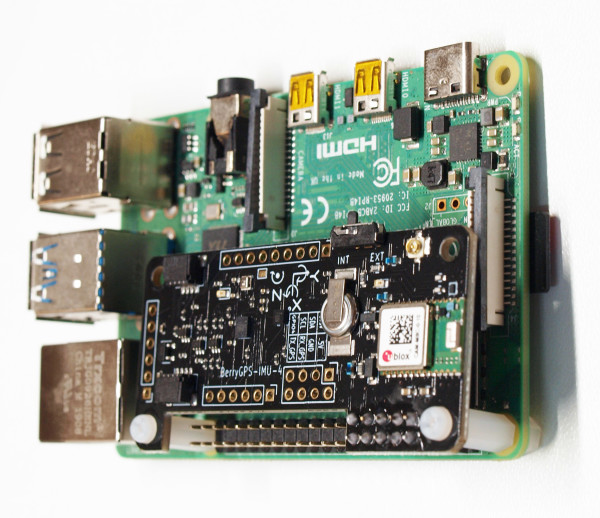
The Berry boards are a mature range of boards from the manufacturer OzzMaker. Here we will focus on the inertial measurement unit (IMU) products BerryIMU and BerryGPS-IMU. Figure 1 shows both boards.
Modern sensor chips are usually only addressable on a limited number of I2C addresses in the interest of attaining higher pin density. The sensors included on the BerryIMU and listed in Table 1 usually offer two different address options.

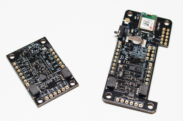
Thanks to the jumpers on the underside of the boards (Figure 2), the I2C addresses can be configured by applying a small drop of solder. The boards also work with the 3.3 V supply of a Raspberry Pi as well as the 5 V of the Arduino world. BerryIMU V3 is a special case as it not only communicates via I2C but the connection can be switched to SPI interface by setting one of the jumpers.
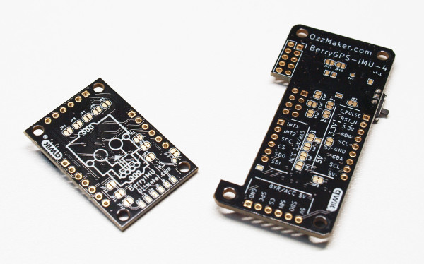
I found the connection solution shown in Figure 3, which allows the IMU board to be connected to an Raspberry Pi, really quite amusing. Berry boards are somewhat recalcitrant when it comes to Raspberry Pi interfacing. I wanted to use a Model 4B as this was the device on my desk at the time. When connecting the BerryIMU, you have to pay close attention that the small adapter board is placed on the header in such a way that the socket opening for the cable connection points away from the Raspberry Pi.
Testing
To search for a Raspberry Pi on the LAN it is a good idea to use nmap. The command nmap -sP 192.168.1.1/24 finds Raspberry Pis connected to the network even without screens connected to them.
The next step is to put the sensors into operation. The Berry boards are well documented and their use in various deployment scenarios is also illustrated. As is often the case, the sample code can be found on GitHub. Since current versions of Raspbian include the git client, the following command is used to pull the code from the repository:
pi@raspberrypi:~ $ git clone http://github.com/ozzmaker/BerryIMU.git
For a first attempt at reading data, python-BerryIMU-gyro-accel-compass is a good choice. Enter the following command:
pi@raspberrypi:~/BerryIMU/python-BerryIMU-gyro-accel-compass $ python3 berryIMU-simple.py
Below is a typical response:
Found BerryIMUv3 (LSM6DSL and LIS3MDL)
Loop Time 0.02 # ACCX Angle 173.62 ACCY Angle 179.06 # # GRYX Angle 0.08 GYRY Angle -0.03 GYRZ Angle 0.02 # # CFangleX Angle 104.20 CFangleY Angle 107.43 # # HEADING 303.92 tiltCompensatedHeading 313.31 #
If you open the main working file of the program you will find the hardware-specific support library:
IMU.detectIMU()
if(IMU.BerryIMUversion == 99):
print(" No BerryIMU found... exiting ")
sys.exit()
IMU.initIMU()
The evaluation of the data takes place in an endless loop calling functions provided by the IMU software. Variables initially cache the results for later use:
while True:
ACCx = IMU.readACCx()
ACCy = IMU.readACCy()
ACCz = IMU.readACCz()
GYRx = IMU.readGYRx()
GYRy = IMU.readGYRy()
GYRz = IMU.readGYRz()
MAGx = IMU.readMAGx()
MAGy = IMU.readMAGy()
MAGz = IMU.readMAGz()
With the library file open you can see that the sample code is a textbook example of how to modularise a Python application. In the header the SMBus module is used that is responsible for interaction with the I2C bus on the Raspberry Pi platform:
import smbus
bus = smbus.SMBus(1)
from LSM9DS0 import *
from LSM9DS1 import *
from LSM6DSL import *
from LIS3MDL import *
import time
Sensors
I have often experienced that the mere interaction with such sensors is only a comparatively small part of the job. However, once you have dug through the data sheets of sensors from other manufacturers, new devices are also quickly understood. What is more critical is the data processing at the higher level.
Fortunately, BerryIMU is particularly well documented. Full use is made of what is possible with a Raspberry Pi, such as using the free version of Wolfram Mathematica analysis software. For reasons of space it is recommended to take a look at the Ozzmaker website from where Figure 4 also originates.
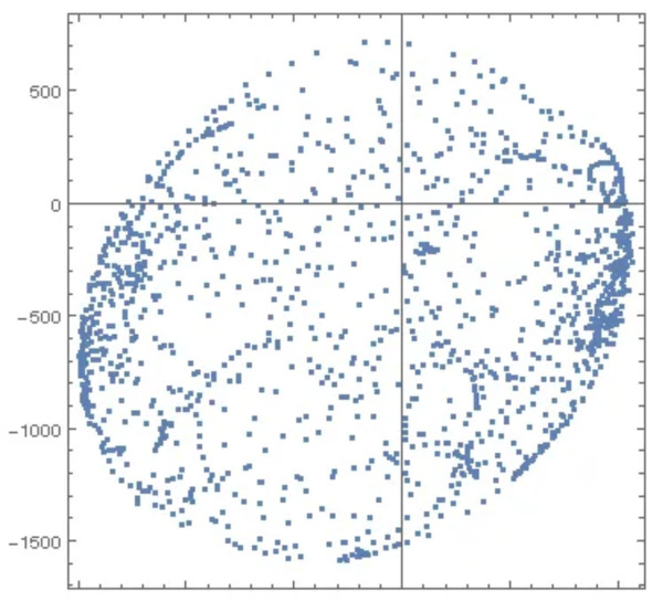
Among other things the website contains graphs that show the impact caused by hard and soft iron displacement on the compass. This results in an offset of the data or the centre of the point cloud. Hard Iron Distortions (HIDs) are caused by magnetic objects that are permanently in the vicinity of the object. Soft Iron Distortions (SIDs) on the other hand are ferromagnetic and other disturbances, such as that caused by the earth's magnetic field. HIDs only shift the centre point while SIDs distort the normally round shape of the field plot. As you can see, the website has quite a lot of background information to offer.
Drone sensor
The BerryIMU is not well suited for use in drones because the connection with the adapter (Figure 3) cannot be realised in a manner that is vibration proof. The second issue is that this board does not provide GPS data, despite this being important for many applications.
There is, however, an alternative board: the BerryGPS-IMU. To use it, a ten-pin header must first be soldered in place. With a little soldering experience this is not too difficult despite the close proximity of two SMD decoupling capacitors (see also Why solder by hand?).

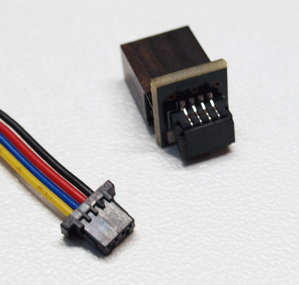
Four sets of screws and nuts are included for the mechanical connection. The holes on the board are intended for the Raspbery Pi Zero. When used with a Raspbery Pi 4 two holes remain unused, as can be seen in Figure 5.
After plugging it in (while switched off), you can power up the system and perform a scan for the board using i2cdetect. This should deliver the same results as the BerryIMU as it has the same sensors.
The BerryGPS-IMU board includes a u-blox GPS module, differentiating it from the smaller BerryIMU. The GPS can make use of either the integrated antenna or an external one, something that is configured via a switch. The round, silver object that looks like a battery is actually a supercapacitor to support the short-term intermediate storage of ephemeris data regarding satellite positions. This information helps the GPS receiver to start up and deliver position data more quickly after any short power-down periods.
The actual communication between the GPS module and the host computer takes place via a serial port. With the Raspberry Pi this is somewhat problematic due to small kernel inconsistencies that occur from time to time. You should therefore update the Rapsberry Pi OS before using this board as follows:
pi@raspberrypi ~ $ sudo apt-get update
pi@raspberrypi ~ $ sudo apt-get upgrade
pi@raspberrypi ~ $ sudo reboot
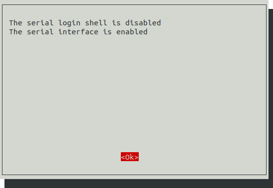
The serial port is then configured via raspi-config. The option Interface Options and then Serial are then selected. As a result, the serial port should no longer offer a login console.
In the next step, the programme asks whether the hardware for the serial port is to be switched on — here the answer is a clear yes. The confirmation shown in Figure 6 then appears. Now only a reboot is necessary to make the new hardware configuration effective.
Understanding GPS Data
Entering the following command will cause the Raspberry Pi to output the data supplied by the GPS module to the command line:
pi@raspberrypi:~ $ cat /dev/serial0
$GPGSV,1,1,00*79
$GLGSV,1,1,00*65
$GNGLL,,,,,,V,N*7A
$GNTXT,01,01,01,NMEA unknown msg*46
The data, provided in NMEA format, is not too complicated. If you want to extract all the information from the GPS data stream you could build your own parser. However, as Linux has long been successfully used as an OS for process computers and controllers there is now an extensive infrastructure for processing geo-data. Those who integrate a GPS module can make use of third-party applications to process the data quickly and easily.
To set up the data pipeline, you first need a group of packages. Especially important is gpsd (gpsdaemon). This software, which runs in the background, forwards the GPS information on to other software:
pi@raspberrypi:~ $ sudo apt-get install gpsd-clients gpsd -y
After the download is complete, the configuration file has to be modified in a text editor (here pico is used):
pi@raspberrypi:~ $ sudo pico /etc/default/gpsd
Most important is the block Devices:
# Devices gpsd should collect to at boot time.
# They need to be read/writeable, either by user gpsd or the group dialout.
DEVICES=""
- - - - -
# Devices gpsd should collect to at boot time.
# They need to be read/writeable, either by user gpsd or the group dialout.
DEVICES="/dev/serial0"
At this point, the function of the pipeline can be checked using, for example, gpsmon. The result is a graphically attractive overview of the NMEA data:
pi@raspberrypi:~ $ gpsmon
Sensing and Locating Made Simple
Regardless of what you are building, connecting up accelerometers, magnetometers and other sensors is a kind of rite of passage for microcontroller developers, the mastery of which one never regrets. The boards from OzzMaker are ideal not only for experiments but also facilitate practical use thanks to their extensive documentation.
The boards are also well suited for small series production since, in small quantities, they are cheaper than producing your own. All in all, they are to be highly recommended!
Questions or Comments?
Do you have questions or comments regarding this article? Then email the author at tamhan@tamoggemon.com or Elektor at editor@elektor.com.
Discussion (0 comments)