Looking for a portable LCR meter? Check out the exciting features and uses for the DE-5000 LCR meter in our detailed review!
The DER-EE DE-5000 is a portable LCR meter, which means that it’s made to measure inductance, capacitance and resistance of electronic components. Let's check it out!
Overview
The meter has a rugged plastic enclosure and measures approximately 190 x 95 x 52 mm, about the same size as many hand-held multimeters. The DE-5000 is equipped with a large backlit dual display which can simultaneously show two measurement values.
Besides L, C and R values, this meter measures secondary values like dissipation factor (D), quality factor (Q), phase angle (Φ), equivalent series resistance (ESR), and parallel resistance (Rp). Users can select measurement parameters manually, but the DE-5000 defaults to an Auto LCR mode upon startup, which automatically detects and measures the most relevant parameters of a component.
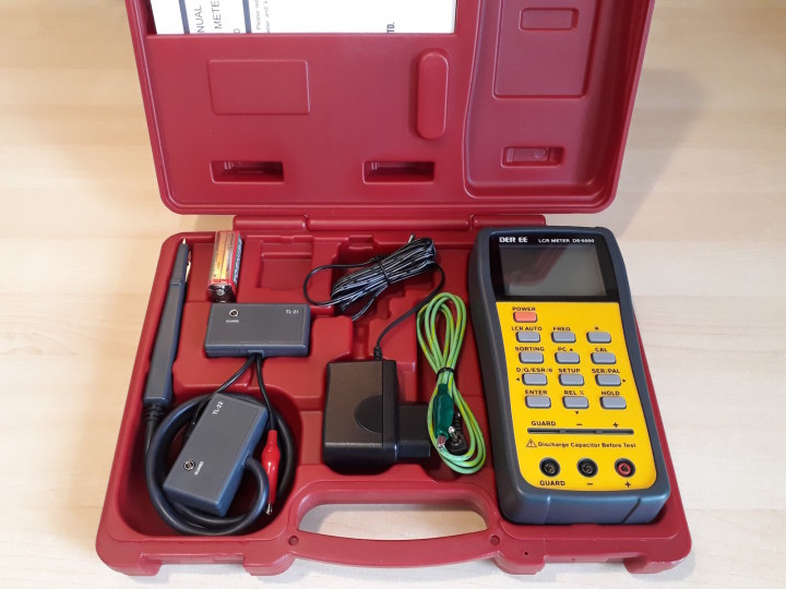
The DE-5000 is powered by an included 9 V battery, or an included DC adapter, which is useful for prolonged use. In terms of accessories, the DE-5000 comes with a rugged carrying case, as well as TL-21 short test leads, TL-22 SMD tweezers, and TL-23 guard line. Additionally, there is an option to connect the device to a PC, but this requires an interface to be purchased separately.
Unboxing of the DE-5000.
What's the DE-5000 For?
An LCR meter such as the DE-5000 can be used for a number of purposes. For troubleshooting and repairing equipment, its thorough measurement of capacitors will be useful. In particular, the dissipation factor D can be a better indicator of a capacitor's health than ESR alone. ESR is often absent in capacitor datasheets, leaving only rough estimates for comparison with our measurements. In contrast, the dissipation factor D is usually better specified.
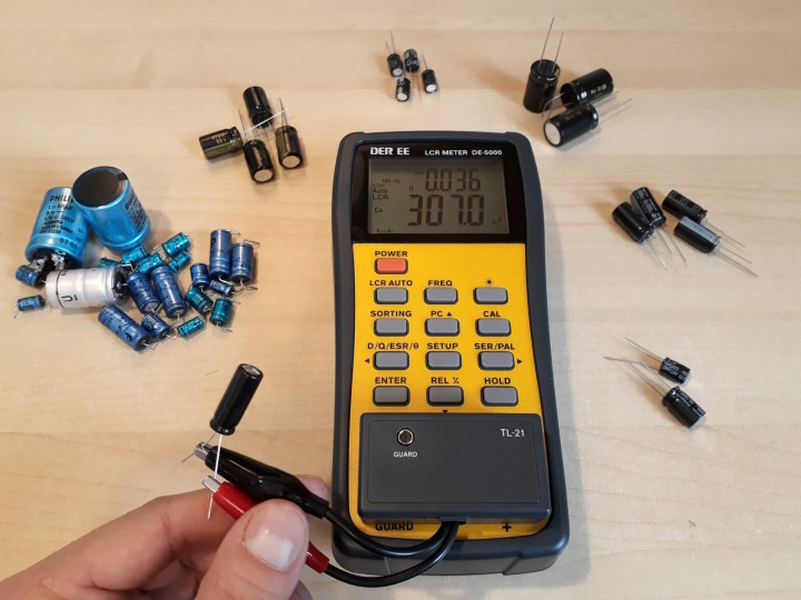
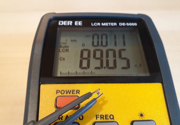
Measuring capacitance and dissipation factor of a capacitor.
This is handy when repairing various types of equipment, such as power supplies, old radio receivers or other vintage electronics, test equipment, or larger machines with electric motors that require start or run capacitors. Speaking of motors, the inductance mode can be used to check motor windings, too.
Another use is to identify unmarked SMD components (often capacitors and inductors), a task made easier with the included SMD tweezers.
Using the SMD tweezers.
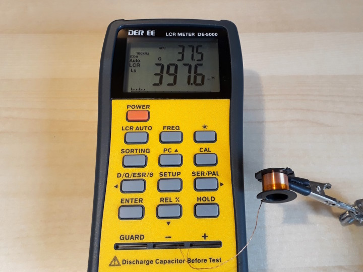
For those interested in studying and making their own DC/DC converters and switch-mode power supplies, the DE-5000's inductance measurements are useful for dealing with inductors and transformers; either measuring existing ones, or winding your own.
When it comes to resistance measurement, while the difference between the DE-5000 and standard multimeters is less pronounced, the former still stands out in measuring very low resistances with its 4-wire Kelvin connection and high resistances up to 200 MΩ.
The Sorting mode can assist the user in quickly sorting components. There are eight different preset tolerances available, with the most narrow being +/- 0.25%. The instrument can then rapidly provide a Pass/Fail indication for swift sorting or verification of components. The Sorting, Setup and Enter buttons are used for this mode, please refer to the manual for more details.
Subscribe
Tag alert: Subscribe to the tag LCR meter and you will receive an e-mail as soon as a new item about it is published on our website!
The Auto LCR Mode
The DE-5000 initially starts in Auto LCR mode at a 1 kHz frequency. In this mode, it automatically identifies the type of component and displays its value in the appropriate unit without the need for any button presses, which is convenient for many applications. Speaking of buttons, this may seem a little confusing at first glance, because only a limited number of buttons are operational.
The LCR Auto button allows you to exit this mode and switch to other modes. The Freq button changes the test signal frequency in five increments: 100 Hz, 120 Hz, 1 kHz, 10 kHz, and 100 kHz. This is important, because the frequency would otherwise remain at 1 kHz by default, and manual frequency adjustment is often necessary, especially for large-value electrolytic capacitors which require a lower frequency. The Backlight and Hold buttons function as expected.
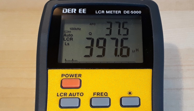
Measuring a custom-made inductor.
The PC button toggles on or off the serial output to the computer through the optional opto-isolated interface, which is not included in the kit and won't be detailed here. Finally, the Cal button enters a calibration mode, which will be explained later.
The other buttons (Sorting, D/Q/ESR/Φ, Setup, Ser/Par, Enter, and Rel) are inactive in Auto LCR mode, which means that to access more details, it is required to enter the other modes, which is done with short presses on the LCR Auto button.
Other Modes
Other modes include Auto L, Auto C, Auto R, and DCR, used for measuring inductance, capacitance, AC resistance, and DC resistance, respectively. You can cycle through D, Q, ESR, and Φ on the secondary display and manually change frequency. The DE-5000 automatically selects the appropriate mode (series or parallel). If you press Ser/Par to modify this parameter, you enter a fully manual mode, which can be both fun and educational!
Series or Parallel?
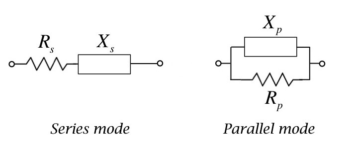
The DE-5000 measures the component's complex impedance and calculates the corresponding L, C, and R values. It assumes the component is modeled as either a reactive component (Xs) in series with a resistance (Rs) or a reactive component (Xp) in parallel with a resistance (Rp). The series model is best for measuring low impedances (small resistors, small inductors, and large capacitors), while the parallel model is suited for high impedances (large resistors, large inductors, and small capacitors). In all the modes named Auto, the DE-5000 can choose the appropriate model automatically.
The two possible models of any impedance; they are equivalent.
Testing Components
You can use the instrument in various ways. Through-hole components fit directly into the + and - slots. The polarity doesn’t matter, even for electrolytic capacitors, because the test signal is AC anyway, and its amplitude is very low. Speaking of capacitors, remember to discharge them fully using an appropriate resistor before measuring them. The DE-5000’s analog frontend will be destroyed by charged capacitors!
Larger components can be connected using the TL-21 adapter, allowing a clip-to-clip distance of up to about 18cm. Surface-mount components are measurable with the TL-22 tweezers. Additionally, custom fixtures or cables can be designed for special needs, using standard 4 mm banana plugs in the instrument's terminals. It's important to keep test leads stationary during and between measurements. Longer test leads have their own inductance and capacitance, which will introduce measurement errors. Fortunately, these can be calibrated out.
Subscribe
Tag alert: Subscribe to the tag Test & Measurement and you will receive an e-mail as soon as a new item about it is published on our website!
Calibration of the DE-5000
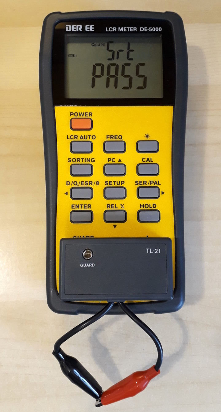
After selecting your test fixture, connect it to the meter and separate the two test leads (like the crocodile clips of the TL-21) with no DUT connected. Press and hold the Cal button for over 2 seconds to start calibration. With the leads apart, press Cal briefly and wait for the countdown. Once Pass is displayed, press Cal again for the next step. When Srt appears, short the two leads together and press Cal . After another countdown and Pass display, press Cal to return to measurement mode.
Calibrating the TL-21 test fixture.
The meter performs internal impedance measurements during these countdowns. One minor annoyance is that each step takes 30 seconds, probably due to averaging multiple measurements for accuracy, but a shorter overall procedure would be preferable.
Is Calibration Really Necessary?
If we want to use the DE-5000 without recalibrating it too often, what kind of errors are introduced? To find out, I calibrated the meter for use without a fixture. The Open part is straightforward, and for the Short part I inserted a bent component lead across the + and - slots. After that, I plugged in the TL-21. That way it’s possible to measure the parasitics of the TL-21 itself. With its test leads open, the parasitic capacitance is measured, and with the crocodile clips shorted together the parasitic inductance is measured. These were under 0.4 pF and under 0.15 µH across all frequencies. Then, I repeated the measurements with the TL-22 SMD tweezers. This time the maximum values were 0.9 pF and 0.2 µH.
These are pretty small values, which means that these errors will be significant only when measuring very small capacitors and inductors. As you can see, the instrument can handle many tasks without frequent recalibration; calibration is only essential when you need highest accuracy or very low resistance measurements. Also, calibration becomes more important when using test leads other than the supplied TL-21 and TL-22.
Who Is It For?
The DE-5000 can be helpful for a range of users, including hobbyists and professionals in electronics. It's particularly useful for those who repair equipment and need to test capacitors, as well as for enthusiasts interested in experimenting with inductors, to build devices such as filters, radio receivers, and DC/DC converters.
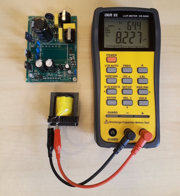
Measuring parameters of a transformer during study of a switch-mode power supply.
This LCR meter can be of interest to electronics hobbyists who already own an assortment of essential tools, such as a multimeter, oscilloscope, power supply, etc., and are seeking more advanced measurement capabilities.
Additionally, it offers a relatively affordable solution for those new to metrology, providing a practical entry point into the field of impedance measurement. As you progress on your electronics journey, you will eventually reach a point in the future where you recognize the need for a more advanced device, often having a clear idea of the specific features you want!
Advantages of the DE-5000
The DE-5000 LCR meter has some nice features. I liked its ability to select test frequencies, as well as the details it gives when testing capacitors, measuring them more thoroughly than a standard multimeter or ESR meter.
In terms of battery life, it draws about 1.7 µA on standby (which is not an issue, as it is less than the self-discharge of the battery alone) and about 13 mA when turned on. This translates to approximately 40 hours of continuous use on a typical 9 V battery. Additionally, for even longer use, a DC adapter is included.
The popularity of this meter on forums and on YouTube acts as an additional resource, offering a wealth of user-generated documentation and support. In particular, some users, who have access to calibrated, lab-grade reference LCR meters, have reported that it performs well within its claimed accuracy specification, up to 0.3% (depending on the range) according to the manufacturer.
For those interested in automated testing from a computer, this LCR meter is compatible with sigrok and can also be used with some Python code available on GitHub, though building or buying an interface is necessary.
Its measuring ranges are quite extended, which makes it capable of measuring both very small and very large values. It's faster to use and more compact than traditional inductance or capacitance bridges, and its auto-ranging feature is quite fast.
The meter also comes standard with a nice selection of accessories, including a rugged carrying case that may seem anecdotal but is actually quite practical for storage. I also liked the included SMD tweezers which were convenient.
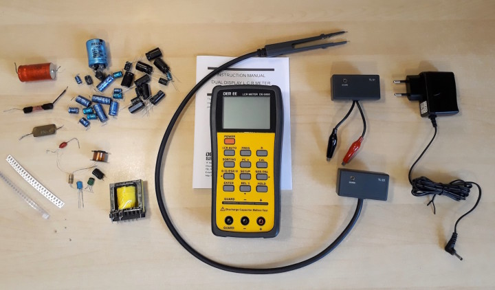
General view of the DE-5000 and some components.
Going Further
I really like this LCR meter and think it's a great addition to my toolkit. It sparked my curiosity about how it works internally. The device applies a sine wave to the DUT’s terminals through an internal series resistor. The meter then measures voltage, current, and phase shift. Based on the phase shift direction, it figures out if the component is capacitive or inductive. From this initial impedance measurement, it can calculate values for L, C, R, D, Φ, etc.
There's a big online community that likes the DE-5000, leading to interesting discussions and suggestions for improvements. A common topic is modifying the TL-21 adapter (maybe a spare one you buy, so you can keep the original) to add longer coaxial test leads and real 4-wire Kelvin clips instead of alligator clips. Or creating a different adapter to switch the DE-5000 to BNC inputs, making it compatible with standard LCR fixtures from other brands. I'll leave the exploring up to you. Have fun!
Elektor Magazine has been one of the leading sources of information on electronics for engineers, designers, start-ups and companies for 65 years. Our magazine is powered by an active community of electronics engineers – from students to professionals – who are passionate about designing and sharing innovative ideas.
For them, we publish hundreds of items a year, in formats such as articles, videos, webinars, and other learning formats. Our mission is to share knowledge in every possible way and inspire readers with the latest developments within the electrical engineering sector.
Thank you for your vote!
Leave further comments in the fields below.
Thank you for your vote!
If you wish to leave a comment with your rating, please first use the login below. If not, just close this window.

Discussion (1 comment)