
Review: Eurocircuits’ Drill/Slot Editor helps you out of holes
Fire up the Buildup Editor
Eurocircuits analyses the board design files to figure out where the drills have to go and what their type is: with or without plating. In many cases this works well, but not always. If it doesn’t, it is time for you to come to the rescue of your design.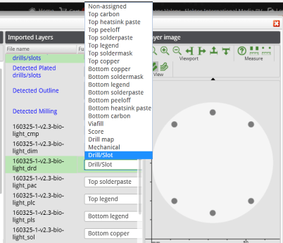
First you have to verify that the drill data is assigned to the correct layers. You do this in the Buildup Selector. Carefully check the layers that the Buildup Selector thinks contain drills and slots. Are they all there? If not, select the layers that have the correct drill/slot data and change their type. Now open the Drill/Slot Editor to edit the drills and slots.
An example
Suppose you have a layer containing one or more slots but they were not detected automatically. This means that you will have to set their properties yourself. To do so is quite simple:- In the Buildup Selector select the layer with the slots you want to add and make it a drill/slot layer;
- Open the Drill/Slot Editor (this will close the Buildup Selector, which is fine);
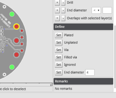
- Select the slots that you want to change by clicking on them or by using the selection buttons on the right;
- In the Define section select the type and/or diameter you want;
- Click Apply when done.
Don't forget to save your work before you order the board.
To be plated or not to be plated
Another common detection problem is when holes have copper around them on both sides of the board. Such holes are detected as plated by convention. Usually this is correct, for instance when the hole is a component hole with traces on both sides of the board, but when it is just a mechanical drill for mounting or orientation plating may not be necessary and even unwanted. In such cases the Drill/Slot Editor can again help you out. Simply select the hole and change its type to unplated.Fix your CAD data
Changing the end diameter (i.e. after plating, if any) of drills is possible too, but this is more of a last-resort option. Use it only when your board designer is on holidays but you really must change the diameter of one or more drills to correct a footprint, and you can’t afford losing any more time. Diameters should, of course, be corrected in the CAD data.Its powerfull, its free, use it!
The PCB Visualizer tool suite by Eurocircuits really is a set of powerful printed circuit board verification tools. Since they are free to use and do not require any purchase, there is absolutely no reason whatsoever to not use them on all your board designs. Of course, any repairs you make inside these tools can only be applied by Eurocircuits, but just highlighting possible problems in your design data is already very valuable. This will help you save time, money and, most importantly, frustration.Watch the video below for another look at the Drill/Slot Editor.
Read full article
Hide full article
Discussion (0 comments)