
The µTracer tube tester kit. Part 2: assembly, step by step
I used a 5-euro no-name adapter which I nonetheless know, is a known-good device. It is FTDI compliant and resides on a virtual COM port. The µTracer GUI when launched for the first time creates a calibration file, which proves the software is functional on your laptop or desktop PC and has the right folder structure installed. The calibration values proper are probably irrelevant at this point. The system is then tested right up to the RS-232 connector at the very cable end, i.e. where the µTracer board is connected.. soon. The test is a simple Ping & Echo check for which a special Debug tool is provided in the µTracer GUI. By linking the TX and RX pins at the µTracer board side you close the comms loop and are able to verify the correct operation of the digital signal path. For meaningful data, we have to wait a while!
I completed all these steps successfully in less than 15 minutes without that wretched “Run time error 8020” popping up at any point. I am running the µTracer GUI on a Lenovo i7-core Windows 7 laptop type U410.
The long way home
Perusing the Construction Manual I noticed it follows a step-by-step assembly approach in which the vast (!) circuitry of the tube tracer is divided into smaller, functional blocks on the board. These blocks get assembled and tested one by one. I admit this approach did not dawn on me until Part 3 in the Manual, after the introduction and the GUI installation and testing.

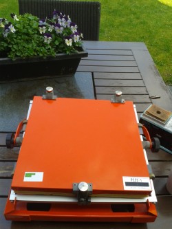
Oh my giddy aunt! That approach conflicts with my bright orange PCB assembly fixture, like this: you cannot follow the established order of first mounting the lower profile parts, then the taller ones, and finally the skyscrapers and oddballs, of the complete circuitry on the board. On the PCB fixture I had, the board is clamped in place and the parts have their legs inserted from the component side. Next you close the lid, which keeps the parts firmly pressed in place by a piece of foam rubber. Then you flip the frame over and at the solder side do all the wire soldering in one pass. Clip off the wire ends, flip over again and you’re ready to insert the slightly higher components.
 I admit I was tempted to not follow the uTracer Construction Manual and mount and solder all parts as described above, i.e. in groups of the same height approximately. But making one error and spending hours on falutfinding and repair is something I did not look forward to. So I opted to follow the exact order of parts mounting outlined in the Manual, to be able to test circuit sections one by one and so “grow confidence” in the final result. Some call this system “eliminate (trouble) by (using) known-good (devices)”
(Ideally) the first two sections…
… to mount on the (perfectly finished) µTracer board are the combined +5 V / +15 V supply section, and the RS-232 interface. Simple stuff I thought I could handle in two late afternoon hours but failed... happily. Mind you, that’s not owing to the kit but rather to the time I spend typing this, working in a location partly outdoors enjoying great weather (!) and making some photos. I am not in a hurry.
I completed all these steps successfully in less than 15 minutes without that wretched “Run time error 8020” popping up at any point. I am running the µTracer GUI on a Lenovo i7-core Windows 7 laptop type U410.
The long way home
Perusing the Construction Manual I noticed it follows a step-by-step assembly approach in which the vast (!) circuitry of the tube tracer is divided into smaller, functional blocks on the board. These blocks get assembled and tested one by one. I admit this approach did not dawn on me until Part 3 in the Manual, after the introduction and the GUI installation and testing.
Oh my giddy aunt! That approach conflicts with my bright orange PCB assembly fixture, like this: you cannot follow the established order of first mounting the lower profile parts, then the taller ones, and finally the skyscrapers and oddballs, of the complete circuitry on the board. On the PCB fixture I had, the board is clamped in place and the parts have their legs inserted from the component side. Next you close the lid, which keeps the parts firmly pressed in place by a piece of foam rubber. Then you flip the frame over and at the solder side do all the wire soldering in one pass. Clip off the wire ends, flip over again and you’re ready to insert the slightly higher components.
I admit I was tempted to not follow the uTracer Construction Manual and mount and solder all parts as described above, i.e. in groups of the same height approximately. But making one error and spending hours on falutfinding and repair is something I did not look forward to. So I opted to follow the exact order of parts mounting outlined in the Manual, to be able to test circuit sections one by one and so “grow confidence” in the final result. Some call this system “eliminate (trouble) by (using) known-good (devices)”(Ideally) the first two sections…
… to mount on the (perfectly finished) µTracer board are the combined +5 V / +15 V supply section, and the RS-232 interface. Simple stuff I thought I could handle in two late afternoon hours but failed... happily. Mind you, that’s not owing to the kit but rather to the time I spend typing this, working in a location partly outdoors enjoying great weather (!) and making some photos. I am not in a hurry.
Read full article
Hide full article
Discussion (0 comments)