Limitless Power: Programmable Power Supply UDP3305S-E delivers 2x 30V and 5A per Channel (review)
Whether you want to test a DIY audio amplifier that doesn't have its own power supply yet, or you're troubleshooting a device suspected of having issues with its associated power adapter, a lab power supply is indispensable. The UNI-T UDP3305S-E provides everything even demanding users need.
Whether it's small projects or complex devices, electronics always require power. Whether you want to test a DIY audio amplifier that doesn't have its own power supply yet, or you're troubleshooting a device suspected of having issues with its associated power adapter, a lab power supply is indispensable. The UNI-T UDP3305S-E provides everything even demanding users need.
Overview and Short Specs of the UDP3305S-E
The Uni-T UDP3305S-E leaves virtually no wishes unfulfilled:
2 channels with 0-30 V, 0-5 A each (Absolute max voltage 2x 33V and current 5.2 A)
The individual channels can be switched in series or parallel. This provides up to 60 V / 5 A, or 30 V / 10 A.
A third channel is intended for supplying digital circuits:
1.8V, 2.5V, 3.3V, and 5V are selectable
Alternatively, a maximum of 3A at 0 and 6V is available
Low Noise USB-A output (5V) at 2A max ("Channel 4")
Large color display (4.3” TFT)
Numerical keypad next to the adjustment wheel for quickly entering values
Versatile programmability:
Power on/off sequences – delay functionality
Arbitrary voltage sequences
Various interfaces: Ethernet, USB, RS232, and 4 digital control pins
SCPI (Standard Commands for Programmable Instruments) compliant
Size and weight: 23 × 36 × 18 cm; 12 kilograms
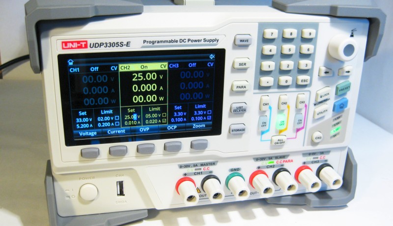
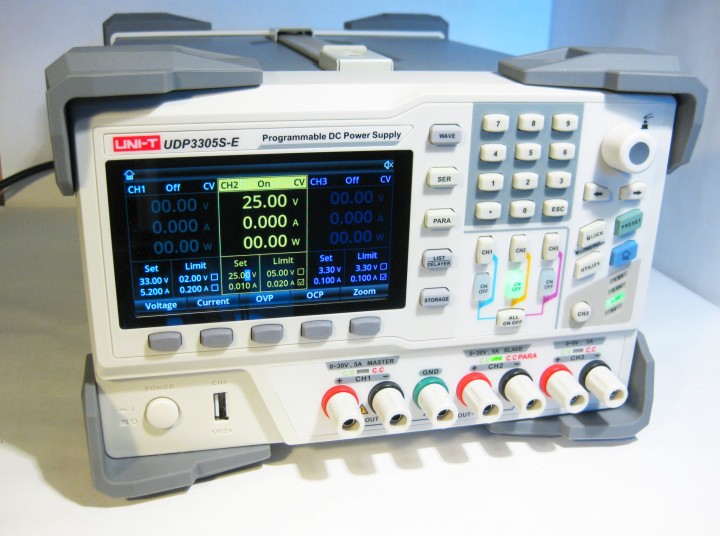
Figure 1. The Uni-T UDP3305S-E Programmable Power Supply
Design and User Interface
The device gives a solid impression. All buttons are made of rubber and provide noticeable tactile feedback. The rotary knob is easy to handle and allows for precise adjustments. The connectors have standard 19 mm (3/4") spacing, but they are not touch-proof safety sockets; they are the standard version.
All relevant data for the three main channels can be displayed clearly and simultaneously on the screen. The functions of all buttons and menus are self-explanatory. The interface can be set to Chinese, English, and German. All menu entries are professionally translated, with some minor exceptions like “Templet” or “Eintreten” for “Enter” in German.
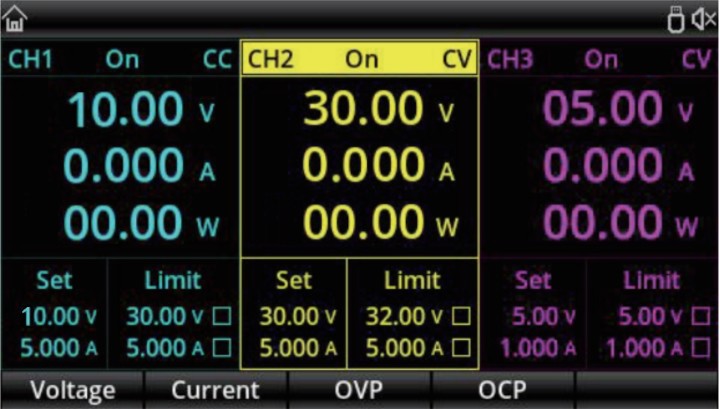
The display shows all modes and information simultaneously:
Voltage, Current, Power for all channels
Constant Voltage (CV) or Constant Current (CC) mode
Sets/Limits for voltage or current
Additionally, all channels have LEDs above the respective connectors, which light up green (CV) or red (CC). Figure 2: TFT Display with all relevant data.
Particularly noteworthy is the numeric keypad, allowing for quick and direct input of values. In many cases, this method is much faster and more precise than turning the encoder wheel.
Additionally, the acoustics are very pleasant: After powering on, the fan starts up smoothly and hums very quietly. Even with an external load of up to 100 W, the fan hardly gets louder.
Subscribe
Tag alert: Subscribe to the tag power supplies and you will receive an e-mail as soon as a new item about it is published on our website!
Serial and Parallel Mode
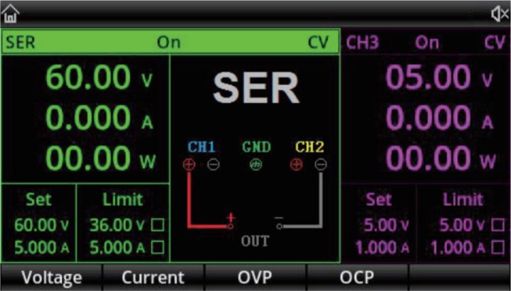
In normal mode, all channels are electrically isolated. Nevertheless, one of the most important features of the device is the ability to couple channels into serial or parallel mode with just one keystroke. In these modes, the following voltages and currents are possible:
Serial: 0… 60 V, 5 A max.
Parallel: 0… 30 V, 10 A max.
If channels 1 and 2 are connected in parallel or series, this is clearly displayed on the screen, and there's a graphic showing how to connect the cables for each mode. Figure 3: Parallel mode display.
Channel 3: Not Only for Digital Electronics and Microcontrollers
In contrast to many competing devices, which often provide just 3.3V or 5V on the 3rd channel, the UNI-T offers a complete channel, including continuous voltage selection and current limiting. Therefore, on channel 3, any voltage from 0 to 6V can be adjusted, with a maximum of 3A.
However, for ease of use, the channel has an additional button with common presets for digital circuits:
U_set = 0 1.8, 2.5, 3.3, 5V
The channel is a complete third output with all features and is not limited to digital electronics or microcontrollers. This makes the UNI-T even more versatile.
Accuracy and Noise of the UDP3305S-E
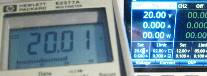
For each channel, a voltage and a maximum current setting can be set. During operation, the measured values are displayed. According to the datasheet, the following tolerances are applicable:
Programming Accuracy:
Voltage: ±(0.03% + 10 mV)
Current: ±(0.2% + 5 mA)
Readback Accuracy:
Voltage: ±(0.03% + 10 mV)
Current: ±(0.15% + 5 mA)
Figure 4: High precision readings.
All measurements (at 5 V, 10 V, 20 V, and 30 V; 0.1 A, 0.5 A, 1 A, 2 A, 3 A, and 5 A) confirm the specified accuracy.
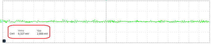
Besides accuracy, ripple and noise are important quality criteria. Ripple refers to the fluctuation caused by the charging and discharging cycles of the power supply output. In a linear power supply, this occurs at the frequency of the mains voltage, i.e., 50 Hz (Europe) or 60 Hz (U.S.). For switch-mode power supplies, the switching frequency dominates the voltage fluctuations.
The specification for the UDP3305S-E states:
Ur: < 350μVrms / 2mVpp
This could also be confirmed: Figure 5: Low noise at the power outputs.
As the figure shows, the measured noise floor (@ 20 V, 3 A output) is well within the specified values.
Current Limit and Protection
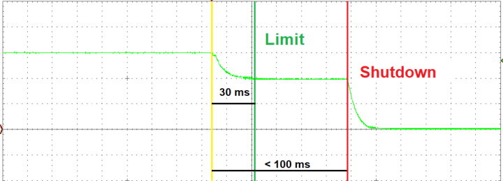
A standard feature of all Lab PSUs is current limiting. If the load demands more current at a specified voltage, the power supply regulates the voltage down to the adjusted maximum current. The faster the power supply achieves this, the better. All channels of the UDP3305S-E (except #4 - USB output) provide precise adjustable current limits and protections.
If the protection limit is not set, the current limit is reached within 30 to 50 ms. If the current limit is active (box at “Limit” is checked), the shutdown occurs within less than 100 ms. Figure 6: Current Limit and Protection Low noise at the power outputs.
As Figure 6 shows, the UNI-T provides a fast current limit and a reasonable shutdown feature. The shutdown time ensures that short current spikes will not trigger the electronic fuse. Unfortunately, this shutdown is not well defined and seems to have different delay times at different current limits. Maybe this will be fixed in a new firmware update.
Subscribe
Tag alert: Subscribe to the tag Prototyping & Production and you will receive an e-mail as soon as a new item about it is published on our website!
Uni-T UDP3305S-E Power On/Off Behavior
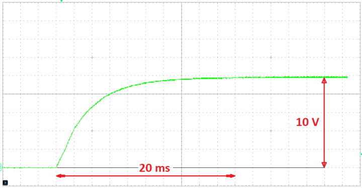
The startup behavior of a PSU is crucial, as even a slight overshoot might damage a sensitive load. Nevertheless, the behavior of the UDP3305S-E is flawless. It shows a smooth voltage rise. Figure 7 presents an example of a 10 V startup on Channel 1.
Figure 7: Typical Start-up for 10 V.
Voltage Stability at Load Change
During a load increase from 0 to 3 A, the output voltage variation is less than 0.2%. This is an excellent value, which is even hard to measure without special lab equipment. A five-digit voltmeter showed the following results:
No Load [V]
3 A Load [V]
30.000
29.997
20.000
19.996
10.000
9.9997
5.000
4.9988
These are very good results. Even the voltage drop in a short piece of wire or in a good connector can be much larger.
Programming and Software Control
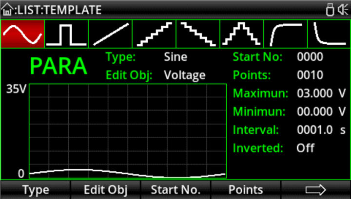
Another great feature is the possibility to program the power supply directly via the user interface. A table with 2048 rows for several parameters is available by pressing the LIST/DELAYER key. Each line can be set to individual values of voltage, current, and time. After starting the procedure, the various settings appear at the outputs of the device. Additionally, there are 8 different templates:
1. Sinus
2. Square Wave
3. Ramp
4. Step up
5. Step down
6. Step up/down
7. Exponential up
8. Exponential down Figure 8: Voltage Sequence Templates.
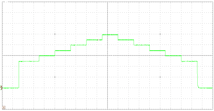
The templates allow for the easy programming of arbitrary voltage or current sequences. Fig. 9 shows an example of a step-up/down sequence. This feature can be very helpful in various test applications. Fig. 9: Step up/down Output Sequence
Via the "UTILITY" -> "Monitor" menu, conditions for three different actions can be set:
Output Off
Warning message
Beeper (sound signal)
This feature is highly useful for supervising circuits with unusual behavior and as an additional safety precaution.
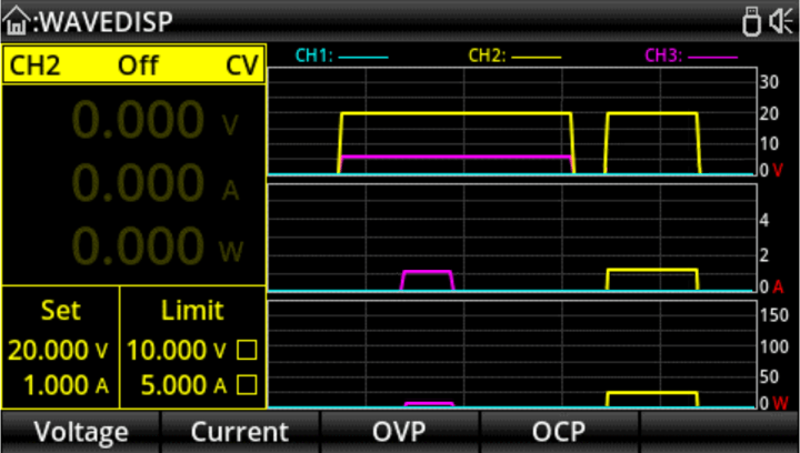
The software also features a waveform display function (key "WAVE"), enabling the simultaneous display of output voltage, current, and power for each channel on the screen. When operating independently, the voltage, current, and power waveforms of all three channels can be viewed simultaneously. In series/parallel mode, the series/parallel channel values are displayed. Figure 10: Waveform display.
This allows for monitoring the current and power conditions of devices under test (DUTs) for a certain period of time. Although the scales cannot be adjusted, this is a useful feature in any test lab.
Software and Firmware
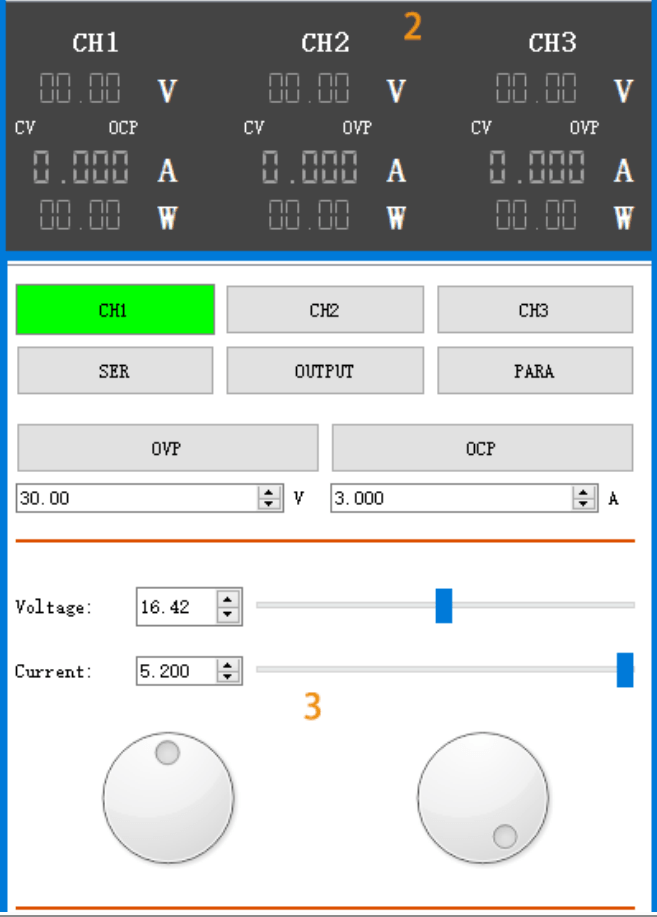
The installation process of the control software available for UNI-T devices is relatively extensive and takes quite some time. However, after successful installation, a graphical user interface (GUI) becomes available. Figure 11: Software user interface.
The interface allows all settings to be remotely controlled via the connected PC. Additionally, parameters for automatic switching ("Delayer") and voltage waveform output ("List") can be set here. When more complex processes are required, it's often easier to perform the programming on the PC rather than on the device itself.
The power supply offers three different interfaces for this purpose:
USB
RS-232
LAN
All three interfaces can control the power supply via corresponding SCPI commands. An accompanying programming manual can be downloaded from the manufacturer's website.
The device is currently shipped with firmware version v1.10. Updates can generally be performed by inserting a USB stick into the USB port on the back. After pressing and holding the UTILITY button, the device must be powered on and the update process starts.
The firmware can be downloaded from the manufacturer's website. Please note that the update has not been tested and is done at your own risk.
The USB output at the backside also serves for saving data tables generated with or for the Delayer/List control.
Pros and Cons of the UDP3305S-E
Pros:
Serial and parallel mode with one keystroke
High total power of up to 328 W
Very low noise and excellent voltage stability
Extensive programming capabilities
Cons:
Only the total voltage is displayed in serial mode; different voltages on the two channels cannot be used (No unsymmetric supply)
No safety banana jacks at voltages up to 64 V!
Sometimes undefined over-current protection
Manual could be improved
Conclusion
The power supply is very intuitive to use and offers a lot of features. The control and power performance are exceptionally good. All in all, a full buy recommendation for enthusiastic makers as well as for professionals.
Elektor Magazine has been one of the leading sources of information on electronics for engineers, designers, start-ups and companies for 65 years. Our magazine is powered by an active community of electronics engineers – from students to professionals – who are passionate about designing and sharing innovative ideas.
For them, we publish hundreds of items a year, in formats such as articles, videos, webinars, and other learning formats. Our mission is to share knowledge in every possible way and inspire readers with the latest developments within the electrical engineering sector.
Thank you for your vote!
Leave further comments in the fields below.
Thank you for your vote!
If you wish to leave a comment with your rating, please first use the login below. If not, just close this window.


Discussion (0 comments)