
A Simple CNCed Enclosure With Autodesk Fusion 360 for Personal Use
on
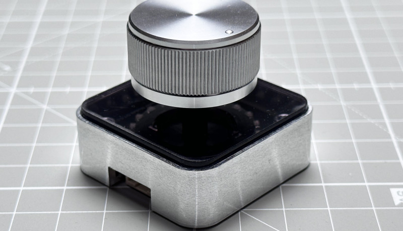
Custom cases for your DIY projects don’t necessarily have to be 3D-printed — they could also be machined out of metal such as aluminum, with a highly professional result. Even if you don’t have your own CNC machine, the manufacturing cost is affordable, the software tools are free, and the steps to follow are simple. In this tutorial, you’ll learn how to create a custom enclosure for the Rotary Encoder Module from DFRobot. With parts common to many enclosures, this should be a great starting point for creating a custom one for your own project.
For modeling, we use Autodesk Fusion 360 for Personal Use. This software is free and intended for hobbyists and non-commercial work. There are some limitations compared to the full (paid) version, but none of them should affect our work.
Tools Used
- Autodesk Fusion 360 (Personal Edition)
Components Used
- Rotary Encoder Module from DF Robot
- Arduino UNO (but any Arduino board will work with the module)
Video Tutorial
Before diving into the individual steps in detail, take a look at the tutorial video:
Steps
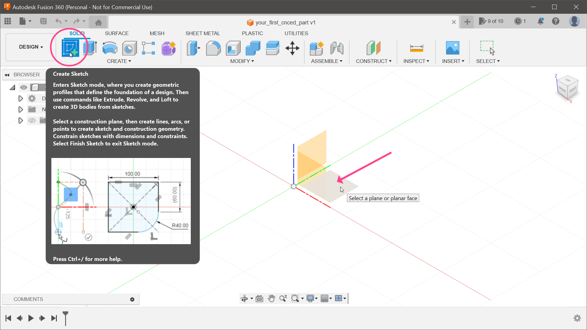
1) The first step in creating any 3D model is starting with a 2D drawing called a Sketch (Figure 1). In Fusion 360, click the Create Sketch button on the toolbar and select a plane upon which to place the sketch. Since our enclosure will be extruded to the top, placing the sketch on the bottom plane in the 3D space makes sense.
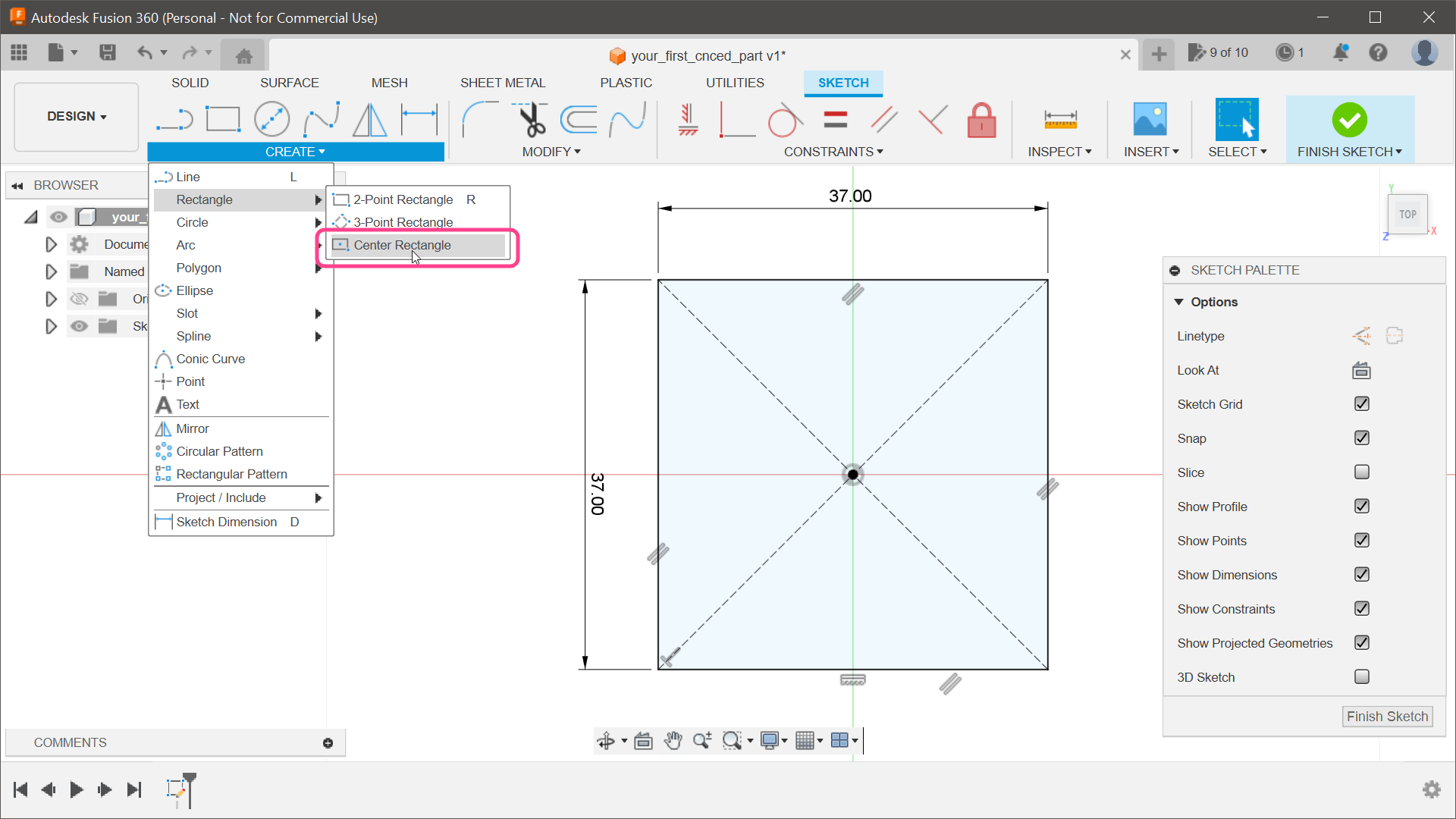
2) Using the caliper, I measured the rotary encoder module size to be 37×37 mm. Let’s create a new rectangle to visualize the PCB’s size (Figure 2). Go to CREATE Rectangle Center Rectangle. Once the tool is active, place the first point on the origin. Use a keyboard to type one dimension (37), jump to the next edit field with the Tab key, and type the second value (37). To complete the creation process, hit the Enter key.
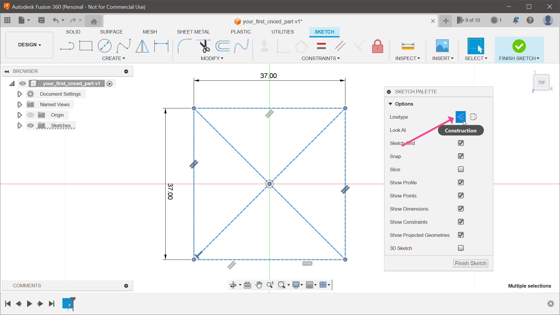
3) We won’t use this shape to extrude the enclosure since we need space around the PCB. It makes sense to select all the lines and turn those into construction lines by clicking the Construction button in the Sketch Palette dialog. This tells Fusion 360 that we use these only as helper lines (Figure 3).
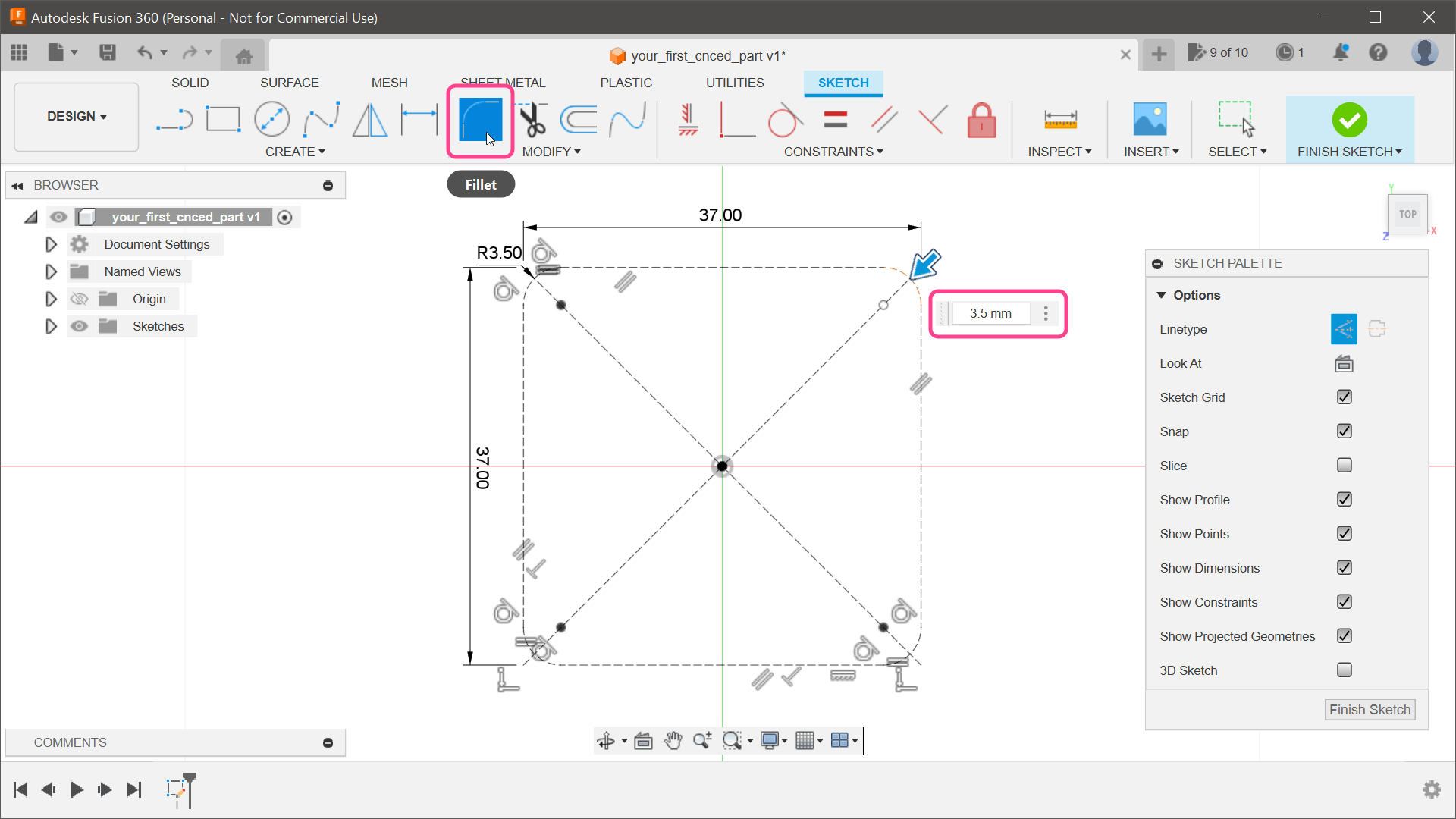
4) The PCB has rounded corners, and it would be nice if our enclosure matched those (Figure 4). A rough measurement shows that the corner radius is about 3.5 mm. In the toolbar, select the Fillet tool, and click on all the outer lines individually. Enter 3.5 mm for Fillet Radius.
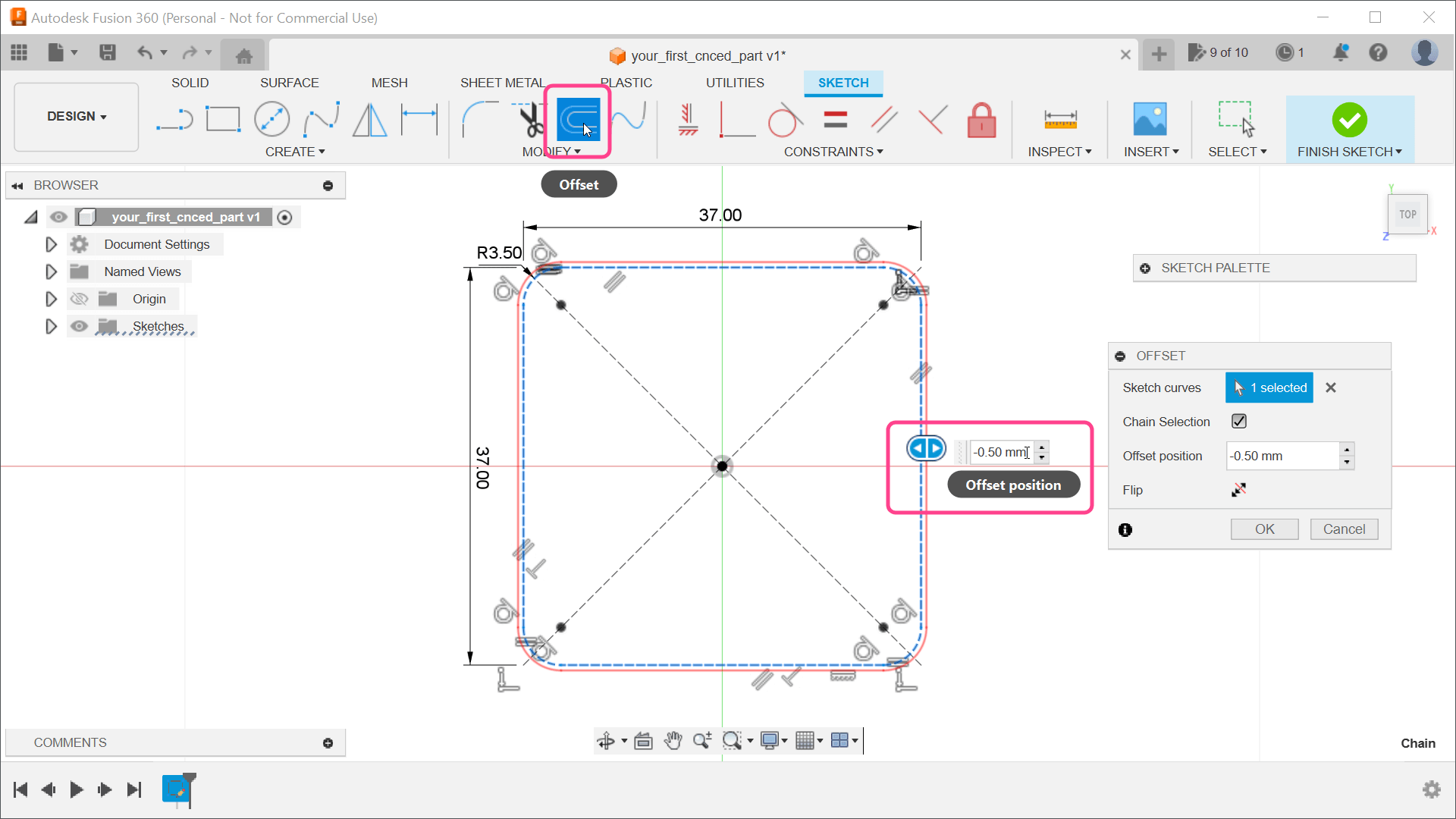
5) We must offset the rounded rectangle to ensure the PCB fits freely (Figure 5). In the toolbar, select the Offset tool and enter a value of -0.5 mm.
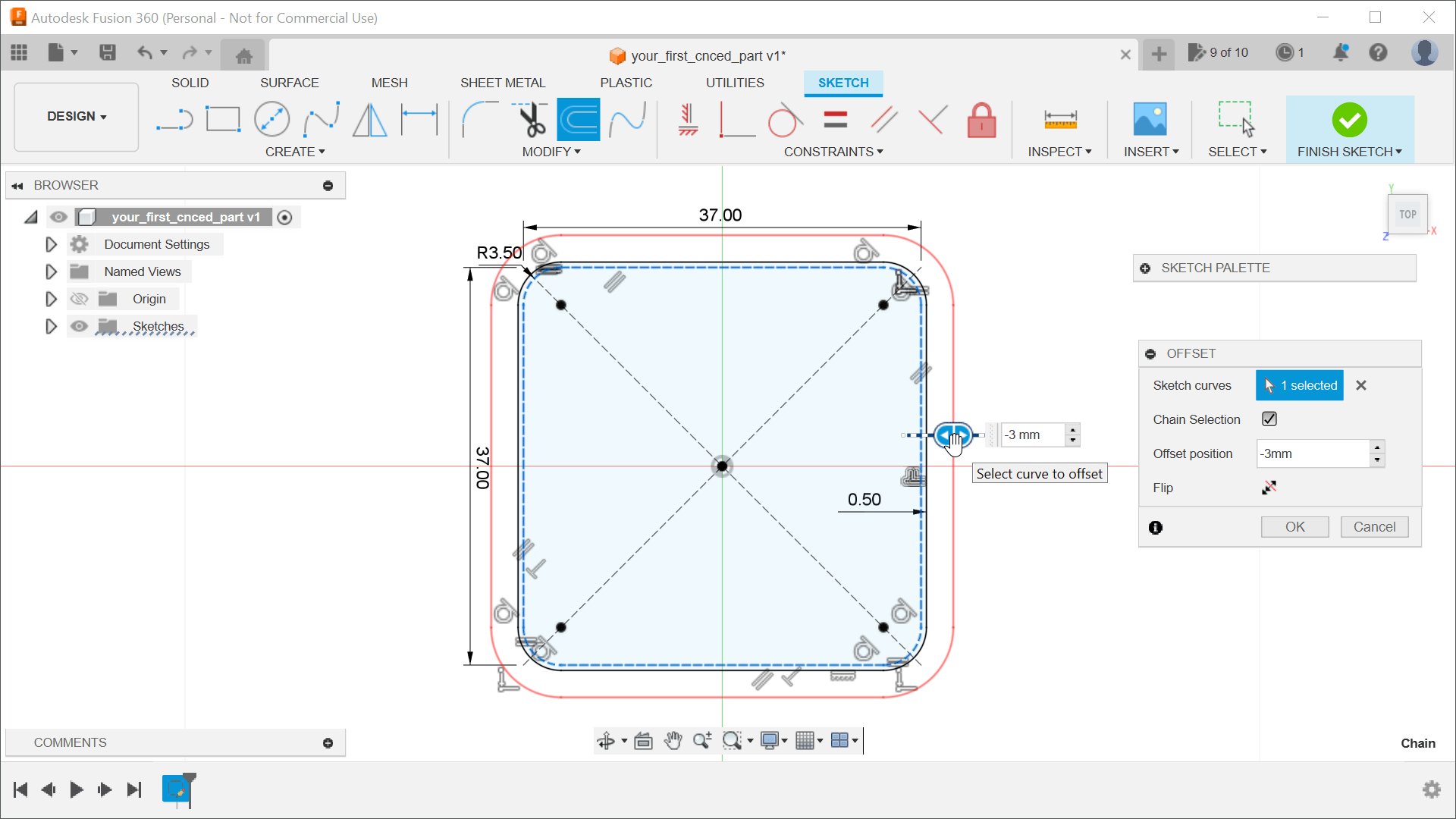
6) Another offset is required to build the walls of our enclosure (Figure 6). Repeat the step again, but enter the offset of -3 mm. This will later create 2.5 mm-thick walls.
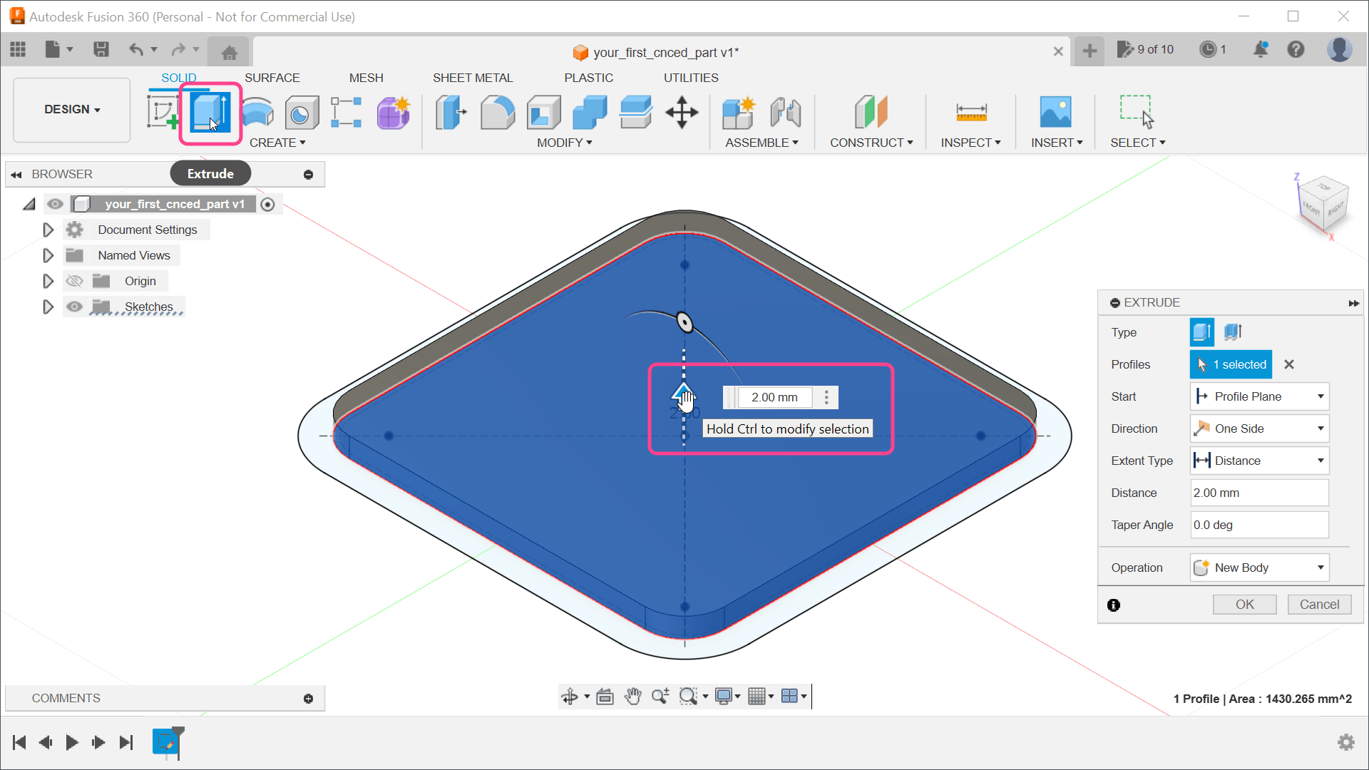
7) We have sufficient shapes to start extruding them. Close sketch editing by clicking the Finish Sketch button, and then select the Extrude tool from the toolbar (Figure 7). Click the inner rounded rectangle on the sketch and enter a distance of 2 mm.
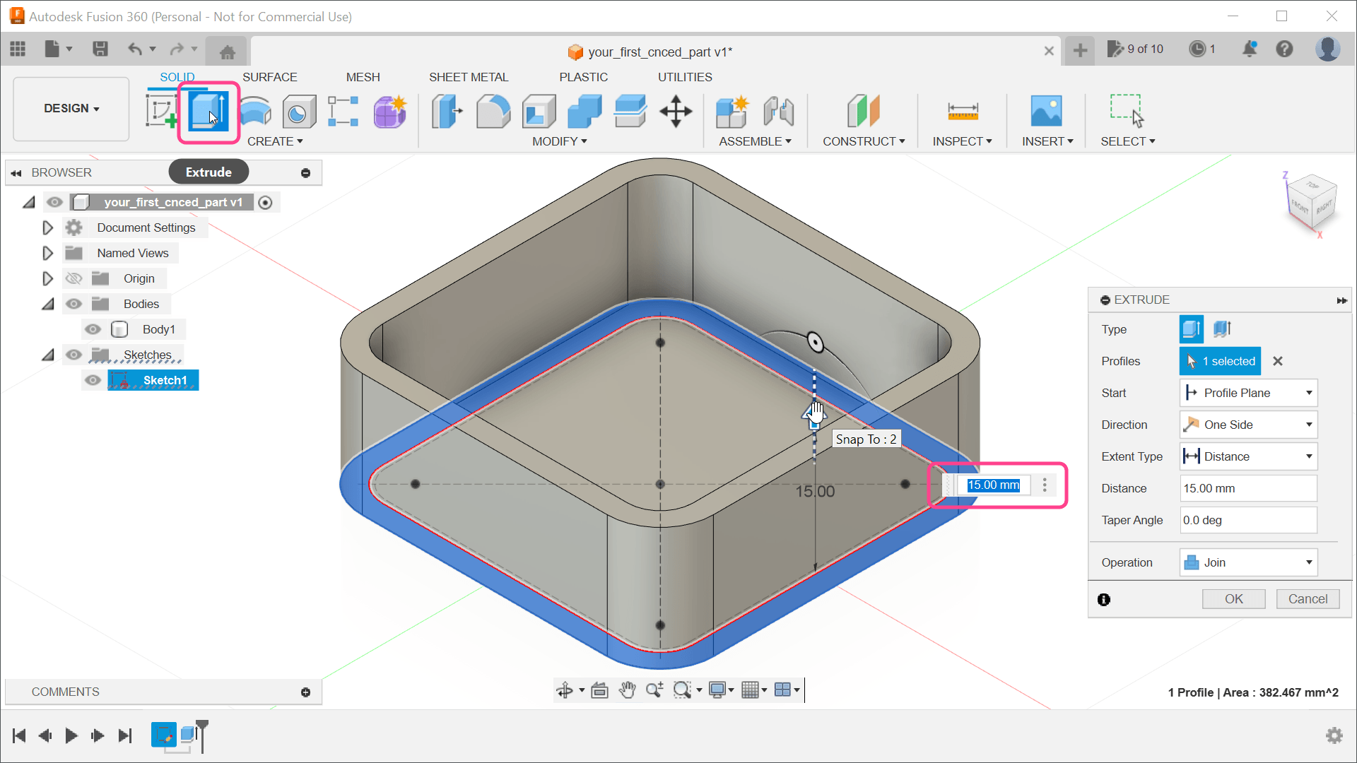
8) We wanted to extrude the walls, but they suddenly disappeared. Don’t worry; it’s just the sketch that’s hidden. In the browser in the top-left corner (Figure 8), open the Sketches group and make Sketch1 visible. Now you can select the Extrude tool from the toolbar and click the outer rounded rectangle. Enter the distance of 15 mm, which will be the height of our enclosure.
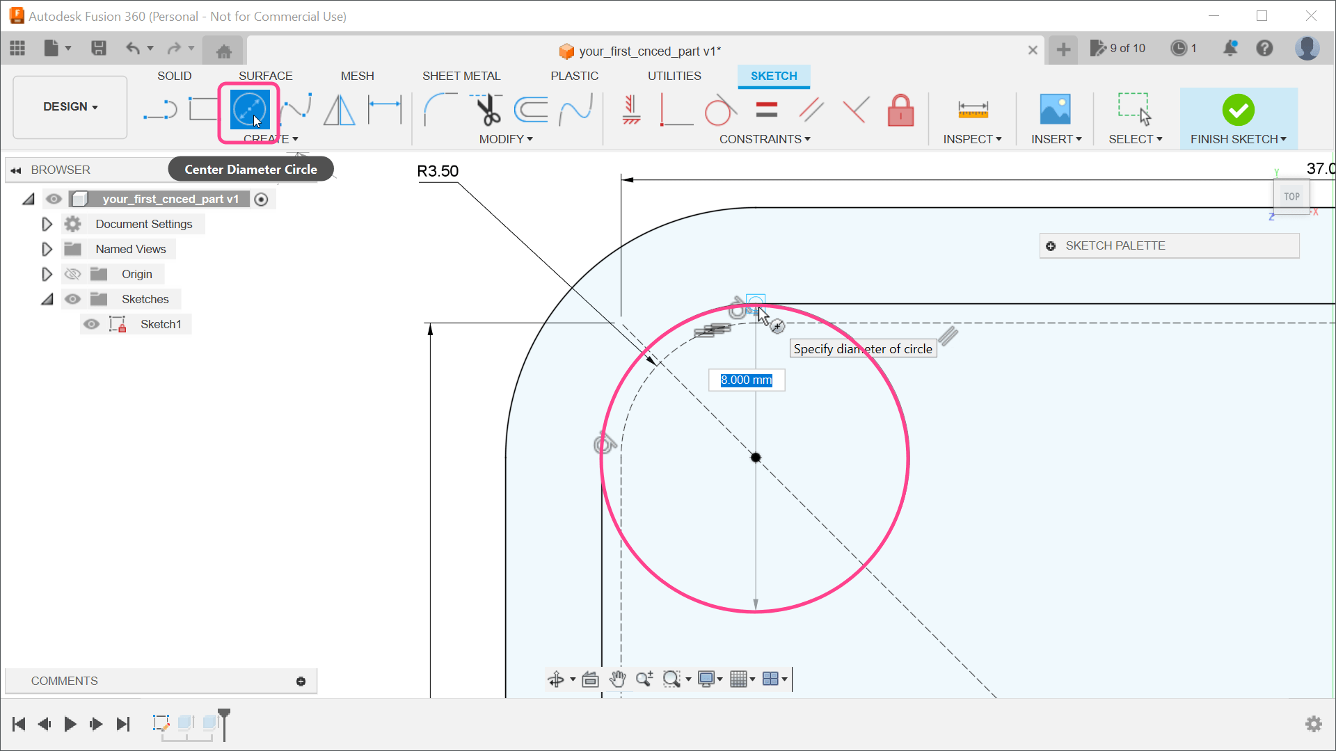
9) The module should sit on supports of some kind, and it would be nice if those supports had holes for screws. For these supports, we need another sketch, but, instead of creating a new one, we can reuse the one we have as well. To return to editing mode, double-click the Sketch item in the browser window. The holes in the PCB are 3 mm in diameter; we need to make the supports bigger than that. For ease of manufacturing, we can even make them big enough to touch the walls of the enclosure. Select the Center Diameter Circle tool from the toolbar and draw a circle in the top-left corner — large enough to touch the inner shell (8 mm diameter) (Figure 9).
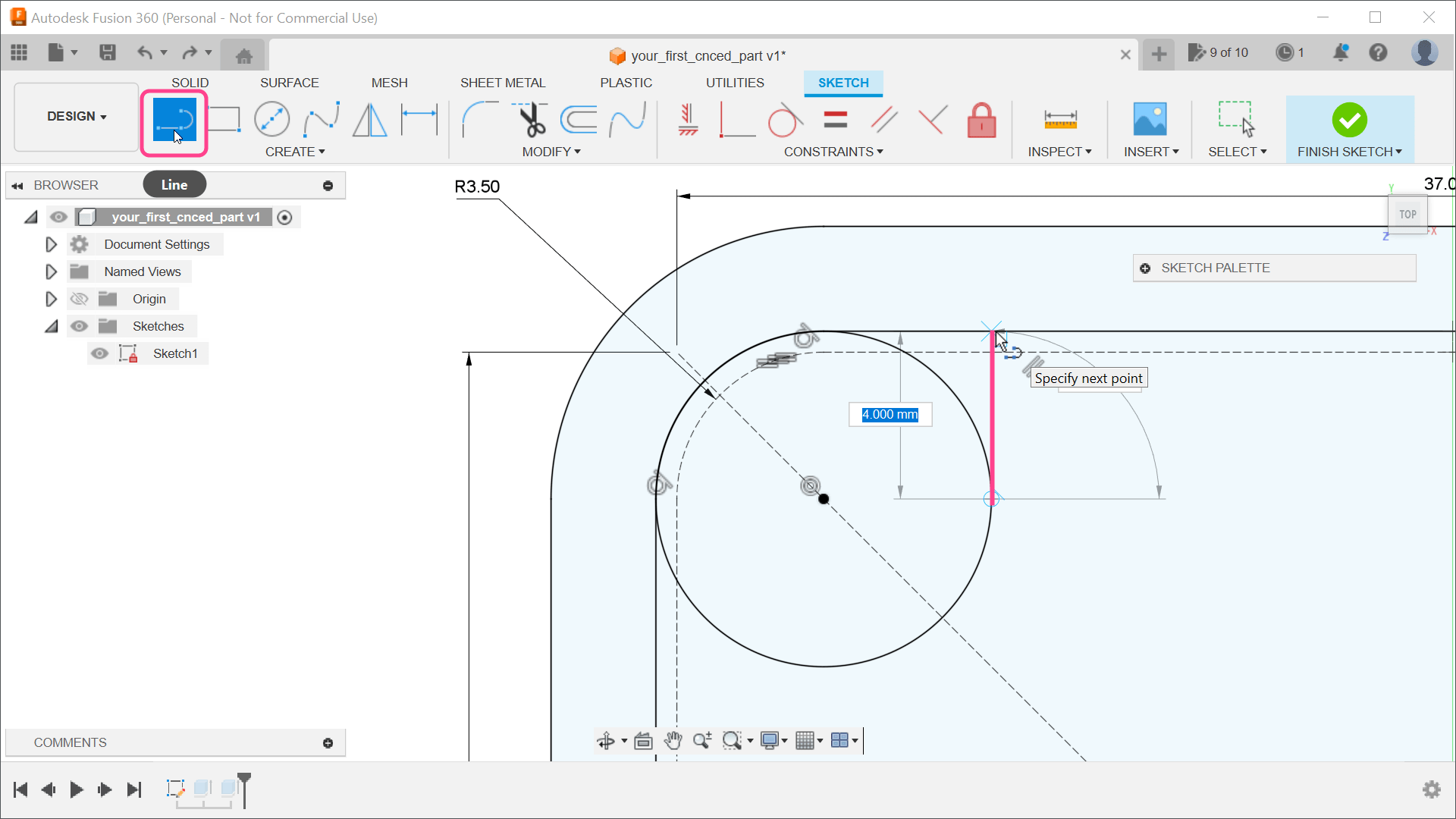
10) The area between the circle and the wall is very thin (Figure 10) and will be difficult to manufacture. We can close it by drawing more shapes with a line tool. In the toolbar, select the Line tool and move the cursor over the circle’s center. After that, keep moving the mouse cursor to the right side until you reach the circle. In that position, draw the first point of the line. Move the mouse cursor to the top until you reach the wall. In that position, draw a second point on the line. Make sure that the movement is somehow straight — that will tell Fusion 360 to add any necessary constraints automatically.
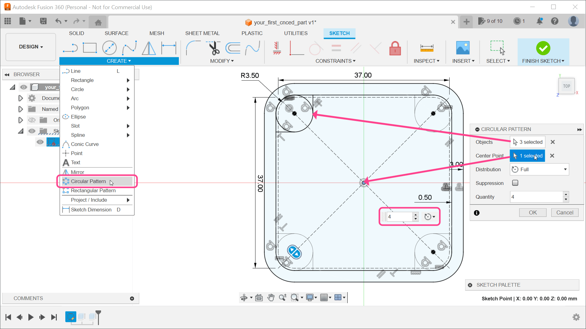
11) Three more supports are needed, but instead of drawing those manually, we can use some tools to duplicate the current support. An obvious choice might be the Mirror tool (CREATE Mirror). However, a one-click solution, in this case, is the Circular Pattern tool, also located in the CREATE menu. With the tool active, we need to select the circle and two lines (Figure 11). Click the Select button next to the center point, and select the origin point. For Quantity, enter a value of 4.
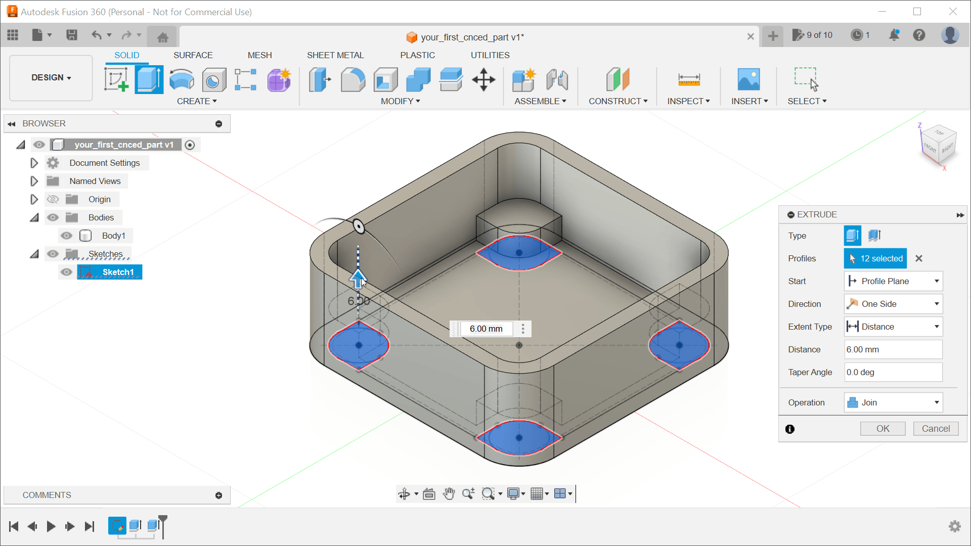
12) At this point, we can again finish editing the sketch by clicking the Finish Sketch button, and we can extrude the supports. With the body visible, it might be hard to select the required faces from the sketch. An easier solution is to hide Body1 temporarily in the browser, select the Extrude tool (Figure 12), and select the shapes from the sketch. However, before extruding, you need to show Body1 for the supports to be connected with this body. The distance should be 6 mm, and, in the Extrude dialog, ensure that the Operation is set to Join.
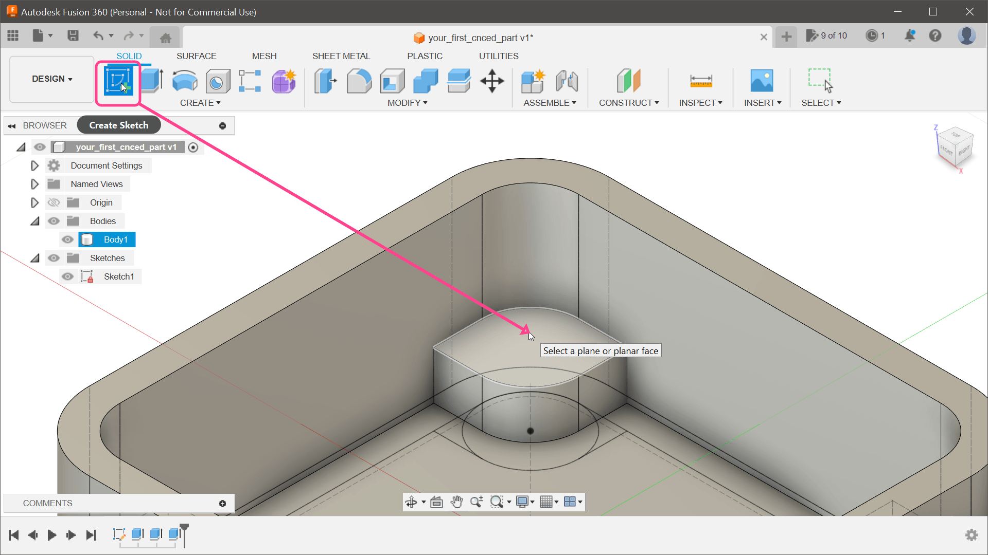
13) It would be nice if those supports included holes for screws. We already have the position of these holes (the center points of the circles), but they are in the different Z positions. The points are on the bottom of the enclosure, but we need those to be on top of the supports. To move those points, we will create a new sketch by selecting Create Sketch button, and, for the position of this sketch, click the top plane of one of the supports (Figure 13).
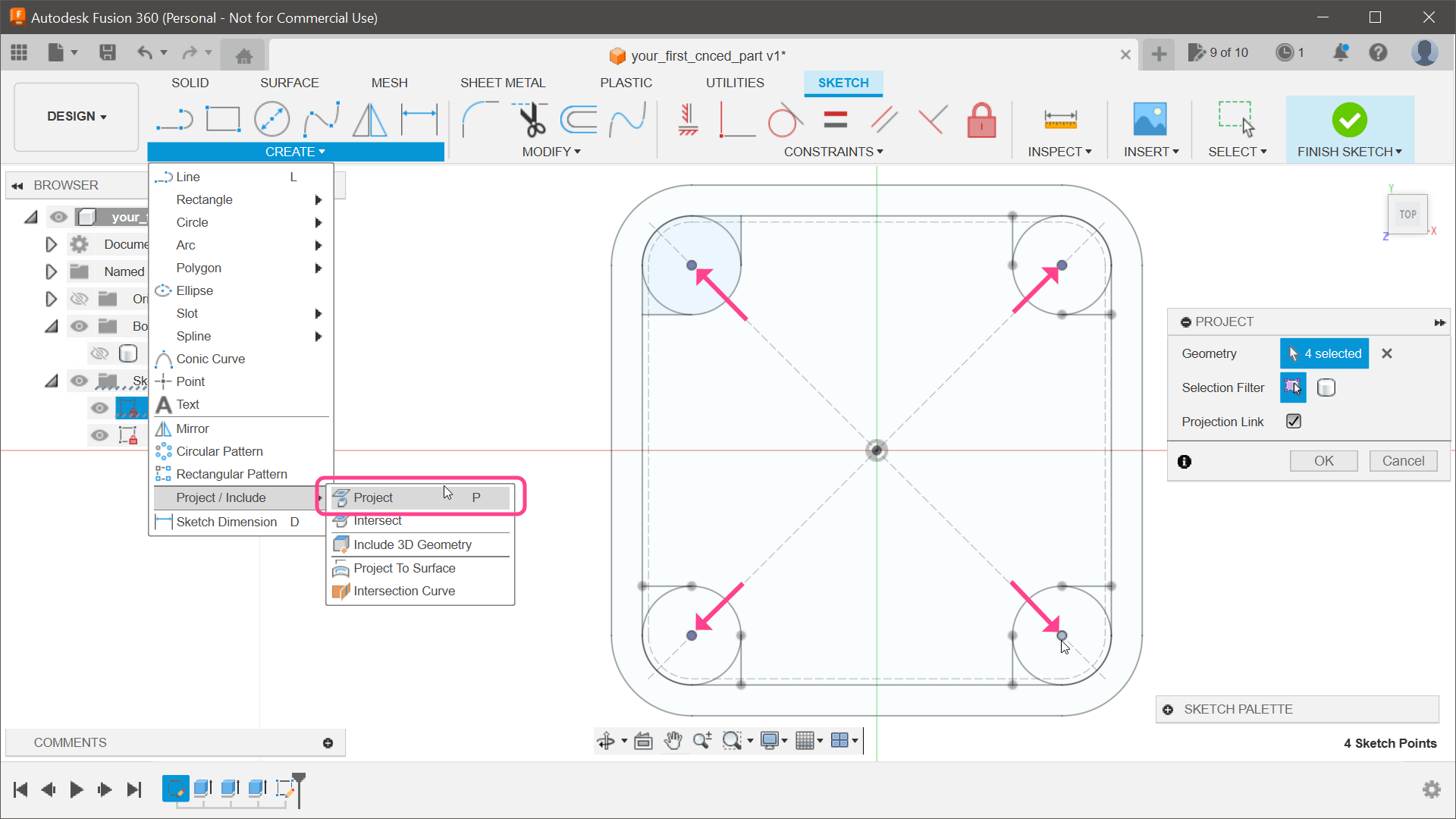
14) To copy those points on our new sketch, select CREATE Project/Include Project (Figure 14). Click on all four points and confirm using the OK button. If you rotate the 3D view, those new points are now hovering over the original sketch.
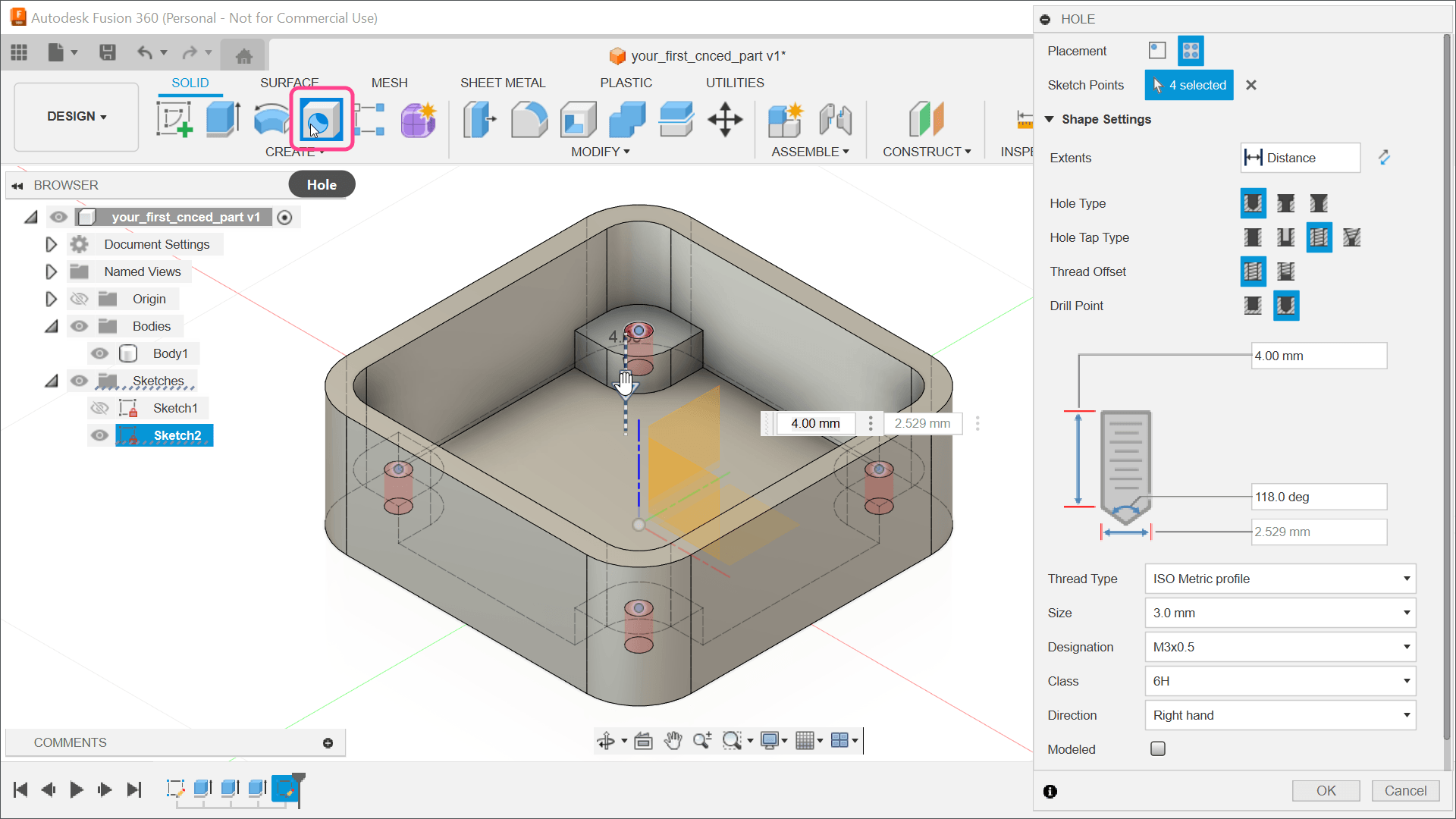
15) Close the sketch, show Body1, and select the Hole tool from the toolbar. Click on all four points and set the Hole (Figure 15). Set Hole Type to Tapped. Thread Type should be ISO Metric profile and Size should be 3.0 mm. As for the depth, we don’t want the holes to go all the way through, and, since the supports are extruded 6 mm over the ground plane, a 4 mm depth should work fine.
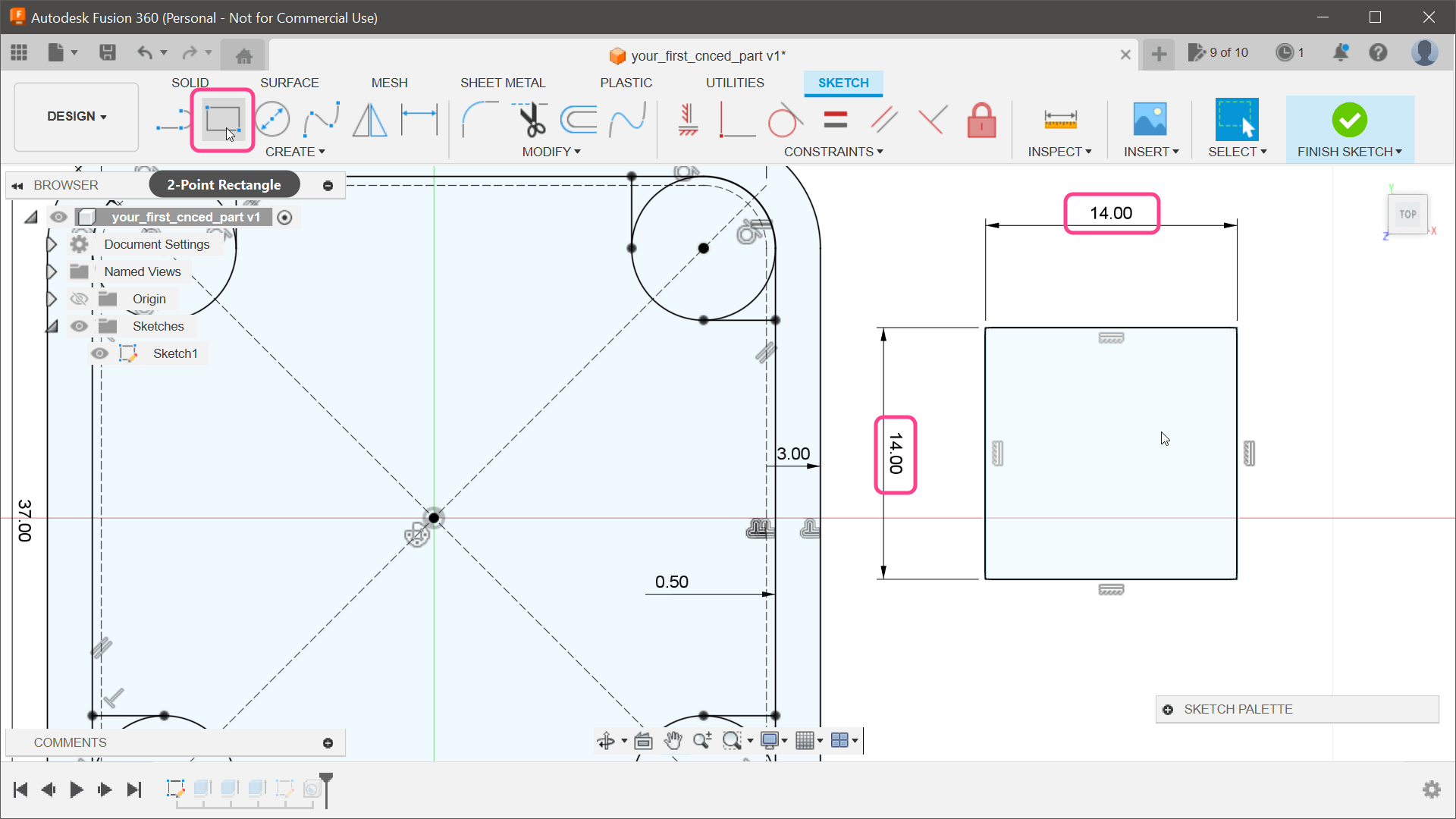
16) We need two rectangular holes on the bottom of the enclosure to access the connectors on the bottom of the PCB. The connectors are slightly different in size, but a 11×14 mm hole will work for both. We need to count with the wall thickness (3 mm), which sets the hole size to 14×14 mm. For drawing those holes, we can reuse our original sketch. Open it for editing and select the 2-Point Rectangle tool (Figure 16) from the toolbar. Draw a 14×14 mm rectangle anywhere on the canvas.
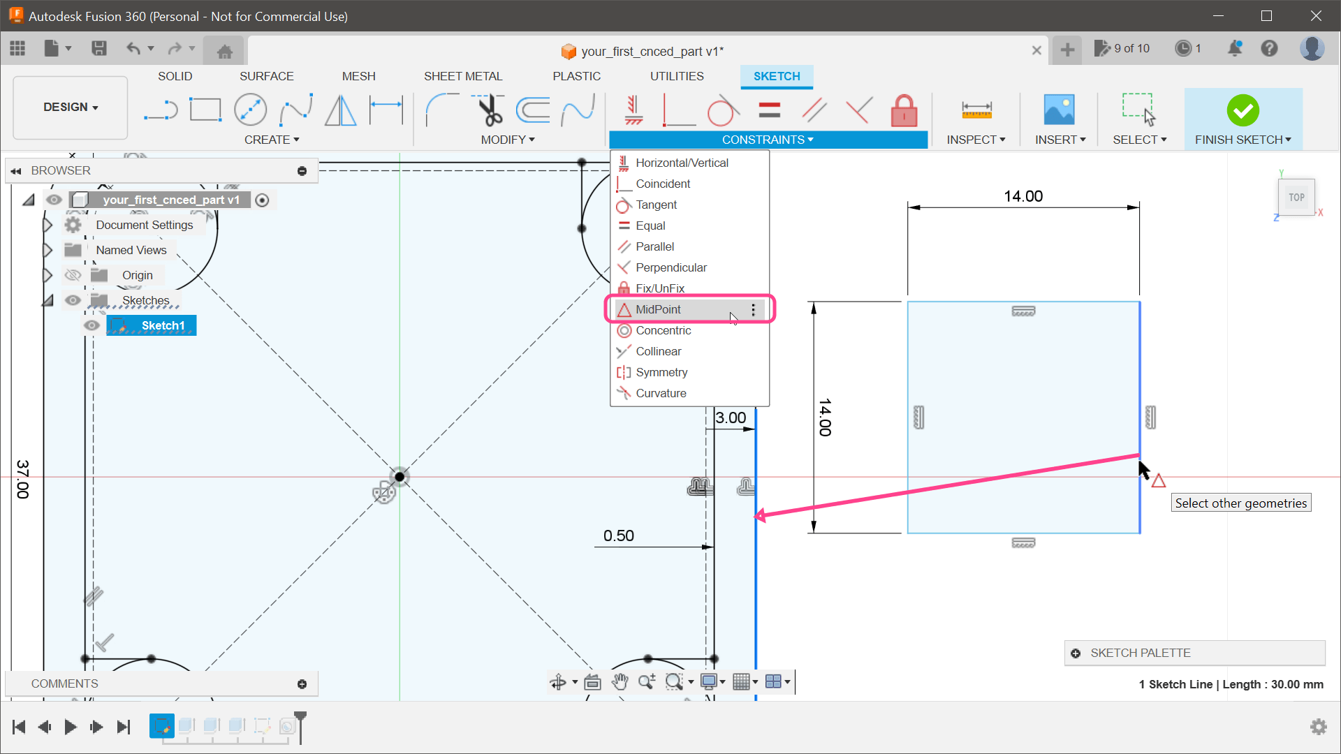
17) To move the rectangle to the correct position, select the MidPoint (Figure 17) constraint from the Constraint group in the toolbar. First, click the right line of the newly created rectangle. Next, click the right line of the wall of the enclosure. This will ensure those two lines are center-aligned and will move the rectangle to the correct position. Repeat the steps for the hole on the left side and close the sketch.
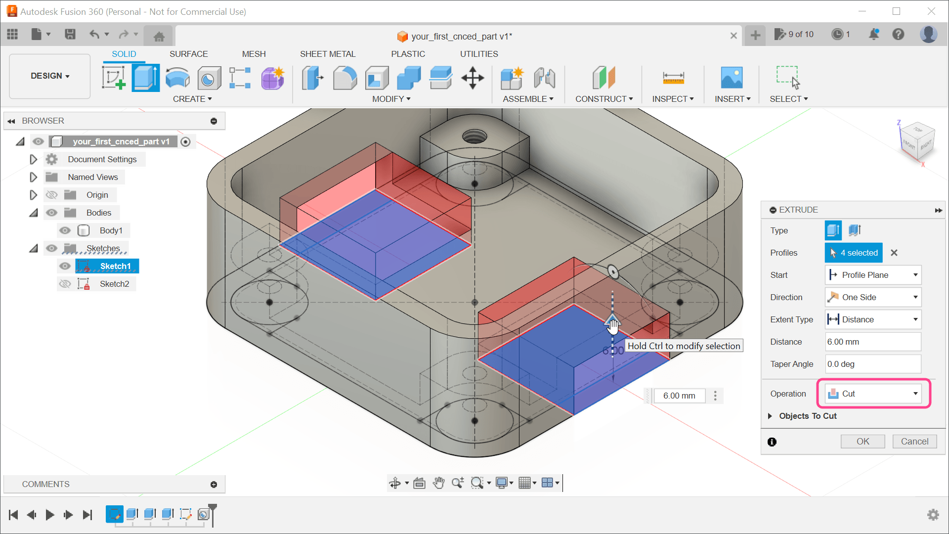
18) Rotate the 3D view to see the bottom of our enclosure. Select the Extrude (Figure 18) tool and then select the newly created rectangles. Enter a distance of 6 mm to match the height of the supports. Operation should be automatically changed to Cut.
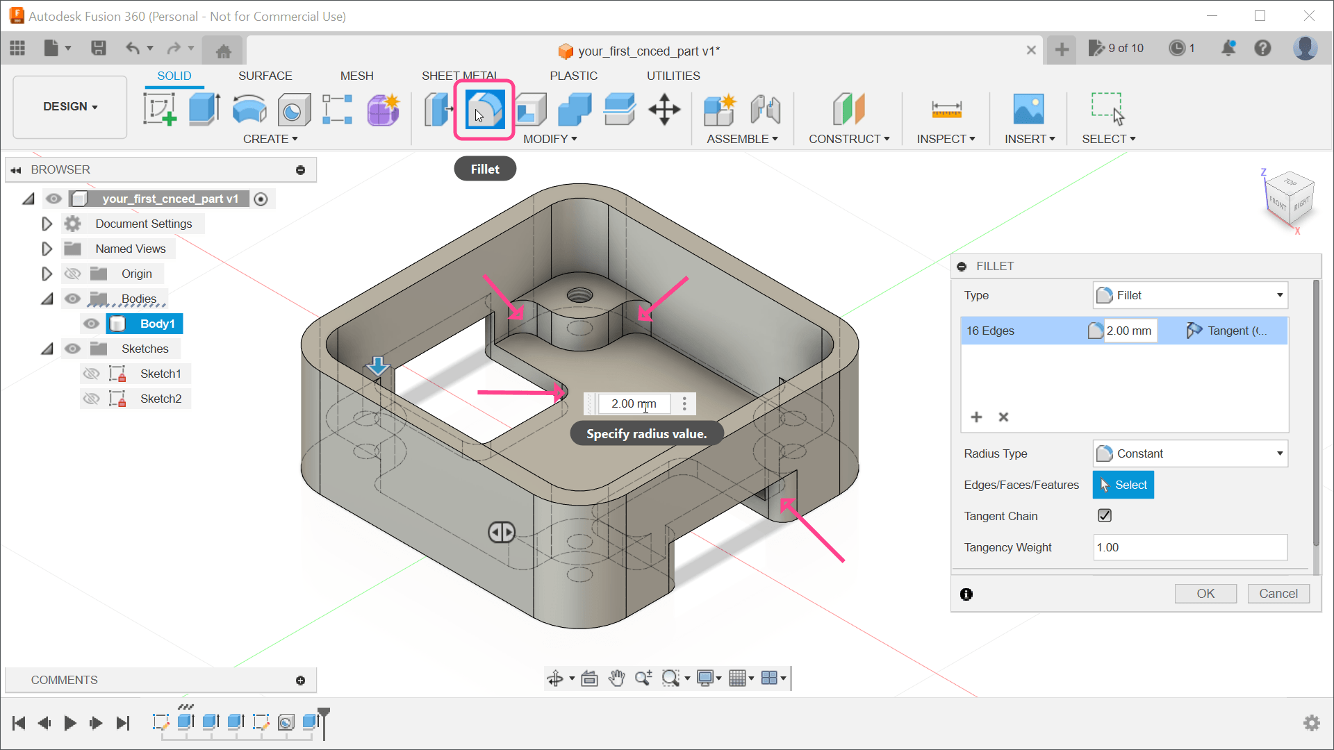
19) The enclosure is almost ready. We have a basic shape, supports with threaded holes, and holes on the bottom of the enclosure to access the connectors. At this point, it might be a good idea to tweak the shape slightly to make manufacturing simpler. Since the milling tool has a certain diameter, it is impossible to create sharp inner edges. We can easily fix this by adding a little rounding using the Fillet (Figure 19) tool from the Modify group. Once the tool is active, select all the hard inner corners and enter some small rounding value — for example, 2 mm.
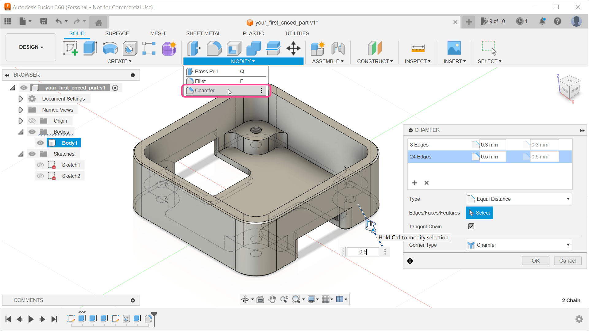
20) The sharp edges on the outside could be smoothened using the Chamfer tool. Select it (Figure 20) from the Modify submenu and select the outer edges of the enclosure. For the top edge, I have used a minimal value of just 0.3 mm. For the bottom edge, a higher value of 0.5 mm was used. You can chamfer multiple edges with different values simultaneously by using the Add Selection Set button in the Chamfer dialog.
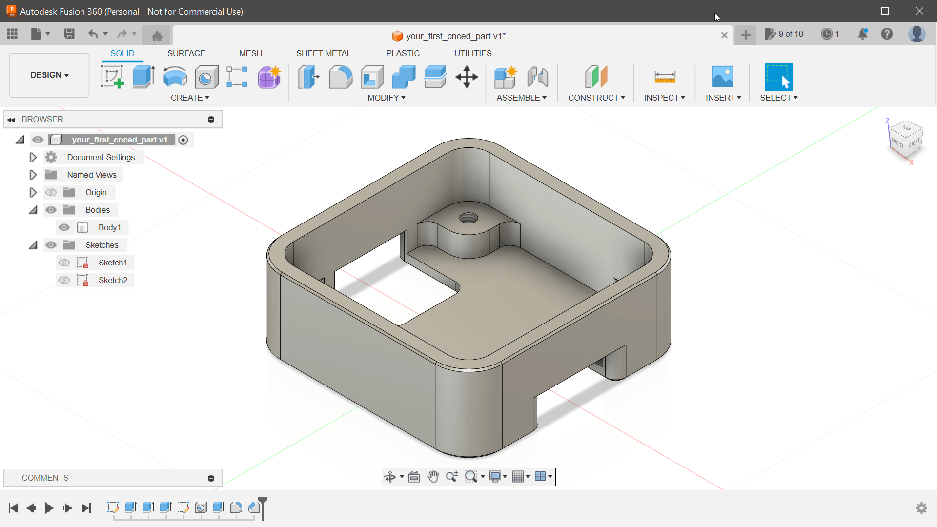
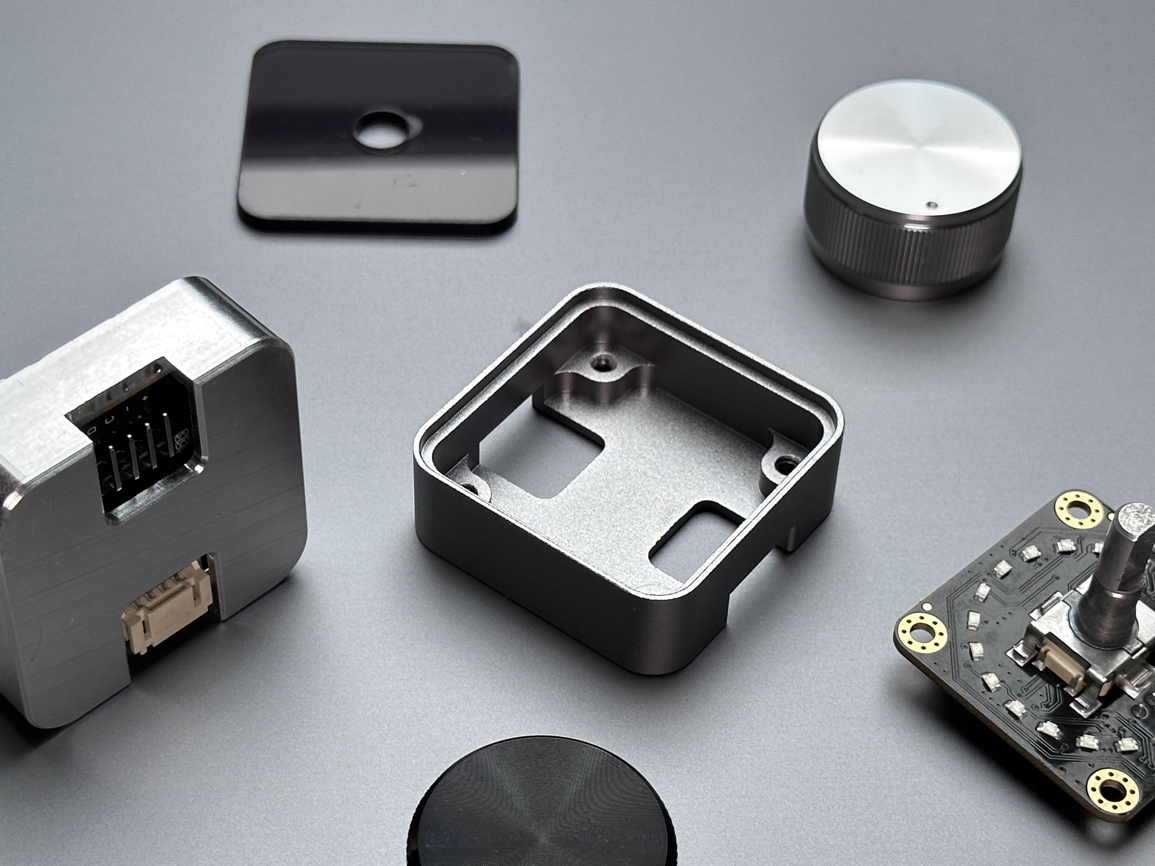
21) At this point (Figure 21), the enclosure is ready to be manufactured. A common file format for 3D drawings is a STEP File (.step), which could be exported using the File Export menu option. With this file, the chosen service provider will mill the real, solid-metal prototype out for you. It is visible with other components in Figure 22 in two different finishes, with the encoder inserted (Figure 23), and finally (Figure 24) as a completed unit. A comprehensive video on this project’s steps can be found here.
It’s That Simple
Autodesk Fusion 360 is a complex application with dozens of tools, but hopefully this tutorial showed you that to create a simple enclosure, you need to use only a few of these tools. The same result can usually be achieved in multiple ways, so as long as it works for you, you don’t need to worry much if it’s the right approach. Every manufacturer will be willing to address any small problems, and if you’re not sure about something, ask. The enclosure from this tutorial was manufactured by PCBway, costing $37 plus shipping. This includes bead blasting of the CNCed part (for a smooth surface) and anodizing (for better surface quality and a nice aesthetic). If you are fine with the raw metal look, you can save a few dollars. And, if you can find a local manufacturer, you can probably save on shipping as well. Good luck creating your own enclosures for your great projects!
About the Author
 Vaclav Krejci published his first (online) tutorial article in 1998 and continued to do so in the following years. After hundreds of tutorials about graphics, he decided to write a book, published in 2007, titled GUI Design in Adobe Photoshop. That led to great work opportunities but, unfortunately, put a long delay on any publishing activities. During Covid (in 2020), Vaclav discovered Arduino and his growing interest in electronics. He has also realized that capturing his learning and turning his findings into tutorials helps Vaclav finish projects that would otherwise be unfinished forever. This time, his main platform is YouTube, with video tutorials. Hopefully, Vaclav’s projects will inspire others on the same journey.
Discussion (0 comments)